ESP32-Based Smart Temperature and Humidity Display with Automated Violet LED Control
Circuit Documentation
Summary
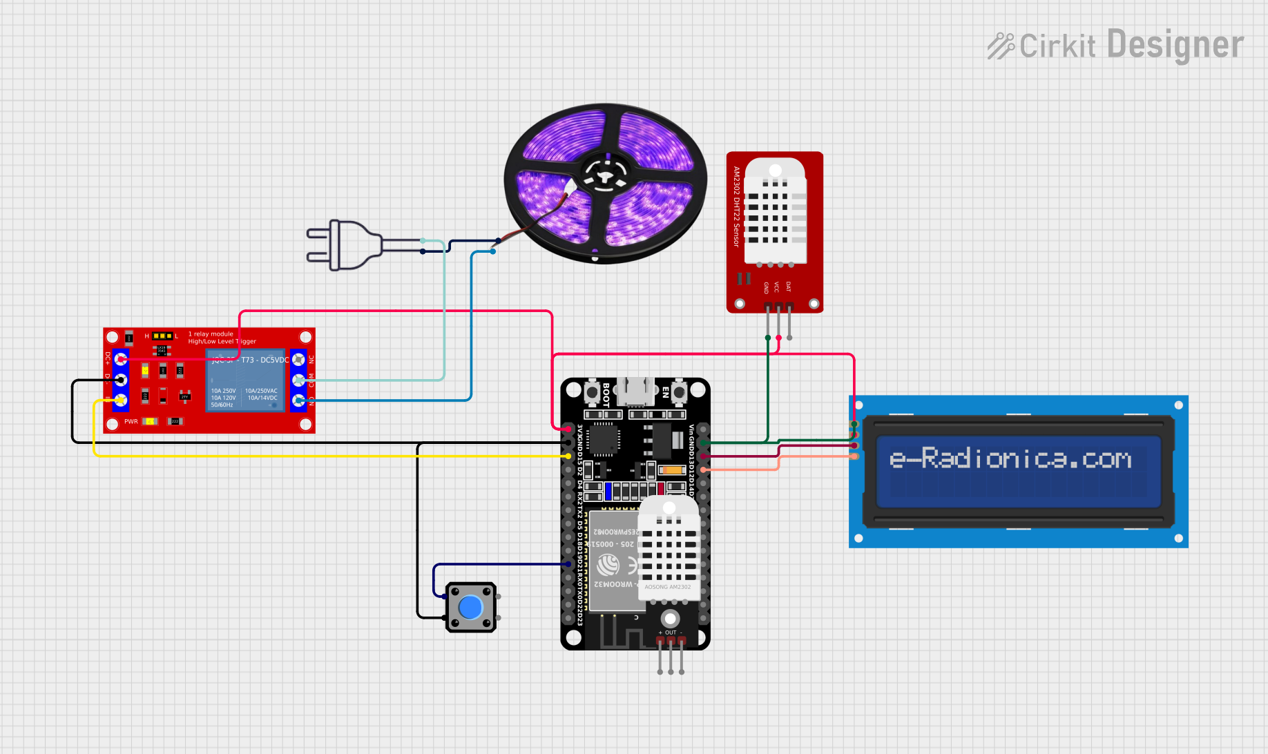
This circuit is designed to interface an ESP32 microcontroller with various peripherals including an LCD screen, a pushbutton, a relay module, LED light strips, and a DHT22 sensor. The ESP32 reads temperature and humidity data from the DHT22 sensor and displays it on the LCD screen. It also controls the state of the LED light strips through the relay module based on the pushbutton input. The LED light strips are powered by a 220V power source, which is switched on and off by the relay.
Component List
ESP32 (30 pin)
- Microcontroller with WiFi and Bluetooth capabilities.
- It has a variety of digital I/O pins and supports I2C communication.
Pushbutton
- A simple switch mechanism for control of a machine or process.
- Typically used to provide user input to the microcontroller.
LED Light Strips (Violet)
- Strips of LEDs that emit violet light.
- Powered by a 220V power source through a relay.
1 Channel 5V Relay Module
- An electrically operated switch that allows you to turn on or off a circuit using voltage and/or current much higher than a microcontroller can handle.
- It is used to control the LED light strips in this circuit.
DHT22
- A sensor for measuring temperature and humidity.
- Provides digital output that can be read by the microcontroller.
LCD screen 16x2 I2C
- An alphanumeric liquid crystal display capable of displaying 16 characters per line in 2 lines.
- Uses I2C communication protocol to interface with the microcontroller.
Power 220V
- The main power source for the LED light strips.
- Provides 220V through the hot wire and neutral wire.
Wiring Details
ESP32 (30 pin)
D12connected toSCLon the LCD screen.D13connected toSDAon the LCD screen.GNDconnected toGNDon the LCD screen,GNDon the DHT22, andVCC- (GND)on the Relay Module.D21connected toPin 2on the Pushbutton.D15connected toINon the Relay Module.3V3connected toVCC+on the Relay Module,VCCon the LCD screen, andVCCon the DHT22.
Pushbutton
Pin 2connected toD21on the ESP32.Pin 3connected toGNDon the ESP32.
LED Light Strips (Violet)
VCCconnected tohot wireon the Power 220V.GNDconnected toN.O.on the Relay Module.
1 Channel 5V Relay Module
INconnected toD15on the ESP32.VCC- (GND)connected toGNDon the ESP32 andPin 3on the Pushbutton.VCC+connected to3V3on the ESP32.N.O.connected toGNDon the LED Light Strips.COMconnected toneutral wireon the Power 220V.
DHT22
GNDconnected toGNDon the ESP32.VCCconnected to3V3on the ESP32.
LCD screen 16x2 I2C
SCLconnected toD12on the ESP32.SDAconnected toD13on the ESP32.VCCconnected to3V3on the ESP32.GNDconnected toGNDon the ESP32.
Documented Code
#include <Adafruit_SSD1306.h>
#include <splash.h>
#include <DHT.h>
#include <DHT_U.h>
#include <Adafruit_Sensor.h>

#include <Wire.h>
#include <Adafruit_GFX.h>

#define SCREEN_WIDTH 128
#define SCREEN_HEIGHT 64

#define OLED_RESET    -1
Adafruit_SSD1306 display(SCREEN_WIDTH, SCREEN_HEIGHT, &Wire, OLED_RESET);

#define DHTPIN 4        // Pin for DHT22 Data
#define DHTTYPE DHT22   // DHT 22 (AM2302)

DHT dht(DHTPIN, DHTTYPE);

const int buttonPin = 12;     // Pin for Push Button
const int relayPin = 13;      // Pin for Relay
bool lampState = false;       // Lamp status (LED)
unsigned long startMillis;
bool buttonPressed = false;

void setup() {
  pinMode(buttonPin, INPUT_PULLUP); // Using internal pull-up
  pinMode(relayPin, OUTPUT);
  digitalWrite(relayPin, LOW); // Turn off relay at start

  Serial.begin(115200);

  if(!display.begin(SSD1306_SWITCHCAPVCC, 0x3C)) {
    Serial.println(F("SSD1306 allocation failed"));
    for(;;);
  }
  display.display();
  delay(2000);
  display.clearDisplay();

  dht.begin();
}

void loop() {
  // Reading temperature and humidity
  float h = dht.readHumidity();
  float t = dht.readTemperature();

  if (isnan(h) || isnan(t)) {
    Serial.println(F("Failed to read from DHT sensor!"));
    return;
  }

  // Displaying results on OLED
  display.clearDisplay();
  display.setTextSize(1);
  display.setTextColor(SSD1306_WHITE);
  display.setCursor(0, 0);
  display.print(F("Temperature: "));
  display.print(t);
  display.println(F(" *C"));

  display.print(F("Humidity: "));
  display.print(h);
  display.println(F(" %"));

  display.display();

  int buttonState = digitalRead(buttonPin);
  if (buttonState == LOW && !buttonPressed) {
    // Button pressed
    buttonPressed = true;
    lampState = !lampState; // Toggle lamp status
    if (lampState) {
      digitalWrite(relayPin, HIGH); // Turn on relay (LED on)
      startMillis = millis(); // Start timing
    }
  }

  if (lampState && (millis() - startMillis >= 10000)) { // 10 minutes = 600000 ms
    digitalWrite(relayPin, LOW); // Turn off relay (LED off)
    lampState = false;
    buttonPressed = false;
  }

  if (buttonState == HIGH) {
    buttonPressed = false; // Reset button status after release
  }

  delay(2000); // Delay for DHT sensor reading
}
This code is designed to run on the ESP32 microcontroller. It initializes the display and DHT22 sensor in the setup() function and continuously reads temperature and humidity data in the loop() function. The data is displayed on the OLED screen. The pushbutton is used to toggle the state of the relay, which controls the LED light strips. The relay is turned off automatically after 10 minutes if it was turned on by the pushbutton.