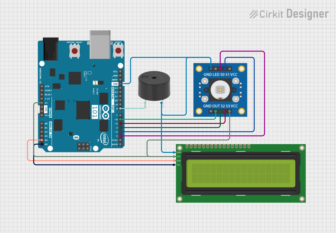
Arduino 101 Based Color Sensing Display with Buzzer Notification

Circuit Documentation
Summary of the Circuit
This circuit integrates an Arduino 101 microcontroller with a TCS3200 color sensor, a 16x2 I2C LCD display, and a buzzer. The Arduino 101 serves as the central processing unit, controlling the color sensor to detect color values, displaying information on the LCD, and driving the buzzer based on certain conditions. The LCD is connected via I2C communication protocol, allowing for simplified two-wire connection. The TCS3200 color sensor interfaces with the Arduino through digital pins for control signals and an output pin for frequency output corresponding to the color intensity. The buzzer is directly driven by a digital pin on the Arduino. The circuit is powered by the Arduino's 5V output, which is distributed to the necessary components.
Component List
Arduino 101
- Microcontroller board based on the Intel Curie
- Pins: A5/SCL, A4/SDA, AREF, GND, D13/SCK, D12/MISO, D11 PWM/MOSI, D10 PWM/SS, D9 PWM, D8, D7, D6 PWM, D5 PWM, D4, D3 PWM, D2, D1/TX, D0/RX, AIN, ioref, RESET, 3V3, 5V, VIN, A0, A1, A2, A3, ICSP MISO, ICSP SCK, ICSP MOSI
TCS3200 Color Sensor
- Color sensor module with frequency output
- Pins: GND, OUT, S2, S3, VCC, LED, S0, S1
16x2 I2C LCD
- Alphanumeric Liquid Crystal Display with I2C interface
- Pins: GND, VCC, SDA, SCL
Buzzer
- Electromechanical component that produces sound
- Pins: PIN, GND
Wiring Details
Arduino 101
- A5/SCL connected to 16x2 I2C LCD SCL
- A4/SDA connected to 16x2 I2C LCD SDA
- GND connected to buzzer GND, TCS3200 GND, and 16x2 I2C LCD GND
- D8 connected to buzzer PIN
- D6 PWM connected to TCS3200 OUT
- D5 PWM connected to TCS3200 S3
- D4 connected to TCS3200 S2
- D3 PWM connected to TCS3200 S1
- D2 connected to TCS3200 S0
- 5V connected to TCS3200 VCC and 16x2 I2C LCD VCC
TCS3200 Color Sensor
- GND connected to Arduino 101 GND
- OUT connected to Arduino 101 D6 PWM
- S3 connected to Arduino 101 D5 PWM
- S2 connected to Arduino 101 D4
- VCC connected to Arduino 101 5V
- S0 connected to Arduino 101 D2
- S1 connected to Arduino 101 D3 PWM
16x2 I2C LCD
- GND connected to Arduino 101 GND
- VCC connected to Arduino 101 5V
- SDA connected to Arduino 101 A4/SDA
- SCL connected to Arduino 101 A5/SCL
Buzzer
- PIN connected to Arduino 101 D8
- GND connected to Arduino 101 GND
Documented Code
No code was provided for the microcontroller. The documentation of the code would typically include a description of the functionality implemented in the code, such as initialization of peripherals, main program loop, interrupt service routines, and any functions for handling specific tasks like sensor readings or display updates. Since no code is available, this section cannot be completed.