
Arduino UNO-Based Spectrophotometer with LCD Display and Stepper Motor
View and Edit Project In Cirkit Designer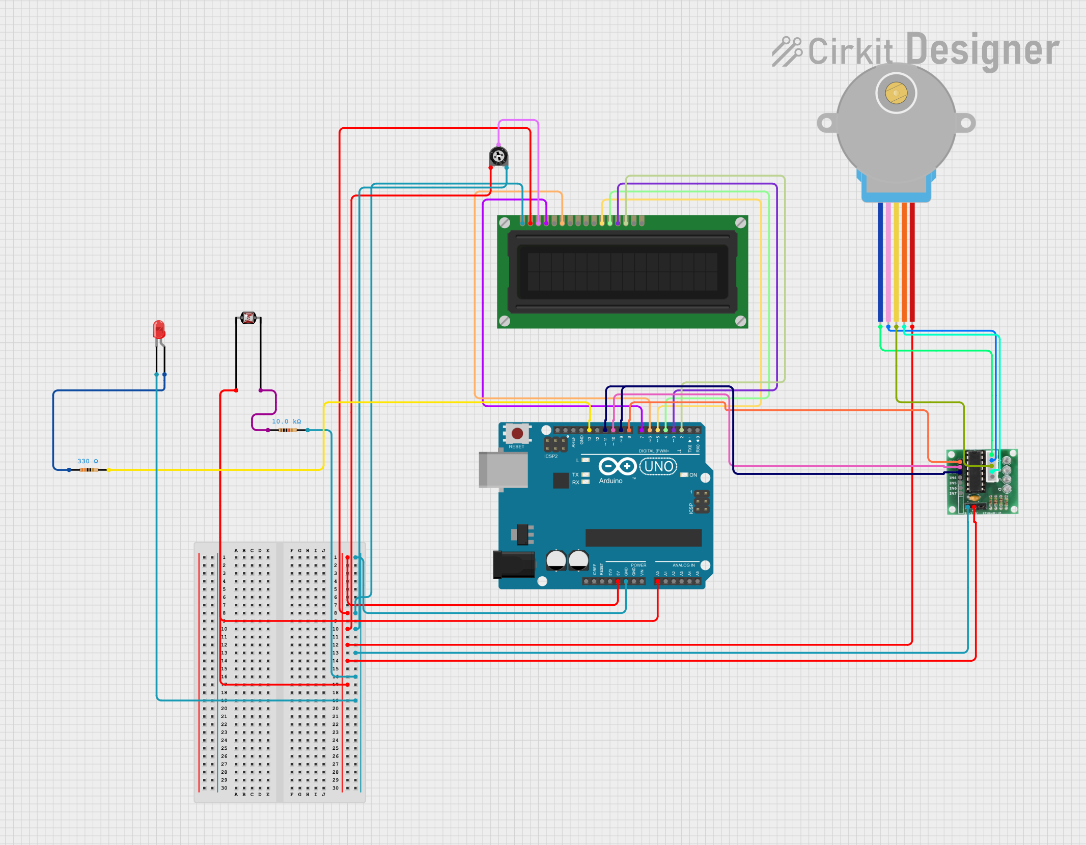
Circuit Documentation
Summary
This circuit is a spectrophotometer system built using an Arduino UNO, an LCD display, a stepper motor, a trimmer potentiometer, a photocell (LDR), resistors, and an LED. The system measures the concentration of a sample by calculating its absorbance using the Beer-Lambert law. The results are displayed on an LCD and the stepper motor is used to move the sample.
Component List
Arduino UNO
- Description: A microcontroller board based on the ATmega328P.
- Pins: UNUSED, IOREF, Reset, 3.3V, 5V, GND, Vin, A0, A1, A2, A3, A4, A5, SCL, SDA, AREF, D13, D12, D11, D10, D9, D8, D7, D6, D5, D4, D3, D2, D1, D0
LCD Display (16 pin)
- Description: A 16x2 character LCD display.
- Pins: VSS, VDD, VO, RS, R_W, E, DB0, DB1, DB2, DB3, DB4, DB5, DB6, DB7, A, K
Trimmer Potentiometer
- Description: A variable resistor used to adjust the contrast of the LCD.
- Pins: leg1, wiper, leg2
- Properties: Resistance: 10000 Ohms
28BYJ-48 Stepper Motor
- Description: A 5V stepper motor used to move the sample.
- Pins: BLUE, PINK, YELLOW, ORANGE, RED
ULN 2003
- Description: A Darlington transistor array used to drive the stepper motor.
- Pins: IN1, IN2, IN3, IN4, IN5, IN6, IN7, GND, +, COIL1, COIL2, COIL3, COIL4, COIL5
Photocell (LDR)
- Description: A light-dependent resistor used to measure light intensity.
- Pins: pin 0, pin 1
Resistor (10k Ohms)
- Description: A resistor used in the voltage divider with the LDR.
- Pins: pin1, pin2
- Properties: Resistance: 10000 Ohms
LED: Two Pin (red)
- Description: A red LED used as the light source.
- Pins: cathode, anode
Resistor (330 Ohms)
- Description: A current-limiting resistor for the LED.
- Pins: pin1, pin2
- Properties: Resistance: 330 Ohms
Wiring Details
Arduino UNO
- 5V: Connected to A0, Photocell (LDR) pin 0, LCD Display VDD, Trimmer Potentiometer leg1, Stepper Motor RED, ULN 2003 +
- GND: Connected to LCD Display VSS, Trimmer Potentiometer leg2, ULN 2003 GND, Resistor (10k Ohms) pin2, LED cathode
- D13: Connected to Resistor (330 Ohms) pin2
- D11: Connected to ULN 2003 IN3
- D10: Connected to ULN 2003 IN2
- D9: Connected to ULN 2003 IN3
- D8: Connected to ULN 2003 IN1
- D7: Connected to LCD Display RS
- D6: Connected to LCD Display E
- D5: Connected to LCD Display DB4
- D4: Connected to LCD Display DB5
- D3: Connected to LCD Display DB6
- D2: Connected to LCD Display DB7
- A0: Connected to Photocell (LDR) pin 0
LCD Display (16 pin)
- VSS: Connected to Arduino UNO GND
- VDD: Connected to Arduino UNO 5V
- VO: Connected to Trimmer Potentiometer wiper
- RS: Connected to Arduino UNO D7
- E: Connected to Arduino UNO D6
- DB4: Connected to Arduino UNO D5
- DB5: Connected to Arduino UNO D4
- DB6: Connected to Arduino UNO D3
- DB7: Connected to Arduino UNO D2
Trimmer Potentiometer
- leg1: Connected to Arduino UNO 5V
- wiper: Connected to LCD Display VO
- leg2: Connected to Arduino UNO GND
28BYJ-48 Stepper Motor
- BLUE: Connected to ULN 2003 COIL1
- PINK: Connected to ULN 2003 COIL2
- YELLOW: Connected to ULN 2003 COIL3
- ORANGE: Connected to ULN 2003 COIL4
- RED: Connected to Arduino UNO 5V
ULN 2003
- IN1: Connected to Arduino UNO D8
- IN2: Connected to Arduino UNO D10
- IN3: Connected to Arduino UNO D11, D9
- GND: Connected to Arduino UNO GND
- +: Connected to Arduino UNO 5V
- COIL1: Connected to Stepper Motor BLUE
- COIL2: Connected to Stepper Motor PINK
- COIL3: Connected to Stepper Motor YELLOW
- COIL4: Connected to Stepper Motor ORANGE
Photocell (LDR)
- pin 0: Connected to Arduino UNO 5V, A0
- pin 1: Connected to Resistor (10k Ohms) pin1
Resistor (10k Ohms)
- pin1: Connected to Photocell (LDR) pin 1
- pin2: Connected to Arduino UNO GND
LED: Two Pin (red)
- cathode: Connected to Arduino UNO GND
- anode: Connected to Resistor (330 Ohms) pin1
Resistor (330 Ohms)
- pin1: Connected to LED anode
- pin2: Connected to Arduino UNO D13
Code Documentation
#include <LiquidCrystal.h>
#include <Stepper.h>
#include <math.h> // For log10 function

// LCD setup: RS, E, D4, D5, D6, D7
LiquidCrystal lcd(7, 6, 5, 4, 3, 2);

// Stepper Motor settings
const int stepsPerRevolution = 2048;
Stepper myStepper(stepsPerRevolution, 8, 10, 9, 11);

// Pin definitions
const int ledPin = 13; // LED pin
const int ldrPin = A0; // LDR pin

// Beer-Lambert law constants
const float e = 80000.0;     // Molar absorptivity (L/(mol·cm))
const float b = 1.2;         // Path length (cm)
const int P0 = 900;          // Initial light intensity

int ldrValue = 0;            // Variable to store LDR reading
float P = 0.0;               // Light intensity after passing through sample
float A = 0.0;               // Absorbance
float c = 0.0;               // Concentration in mol/L
float cMicro = 0.0;          // Concentration in µmol/L

void setup() {
  Serial.begin(9600);           // Start Serial Monitor
  lcd.begin(16, 2);             // Initialize the LCD (16x2)
  pinMode(ledPin, OUTPUT);      // LED as output
  myStepper.setSpeed(10);       // Stepper speed (in RPM)

  // Initial LCD message
  lcd.setCursor(0, 0);
  lcd.print("Spectrophotometer");
  delay(2000); // Display welcome message
  lcd.clear();
}

void loop() {
  // Step 1: LED on and read LDR
  digitalWrite(ledPin, HIGH);  // Turn on LED
  delay(100);                  // Wait for light stabilization
  ldrValue = analogRead(ldrPin); // Read LDR value (simulate P)
  P = map(ldrValue, 0, 1023, 0, 900); // Map LDR value to light intensity range

  // Calculate Absorbance (A) and Concentration (c)
  if (P > 0) { // Ensure P is not zero to avoid division by zero
    A = log10((float)P0 / P); // Absorbance calculation
    c = A / (e * b);