
Arduino and ESP8266 Nodemcu-Based Multi-Sensor Monitoring and Actuation System
View and Edit Project In Cirkit Designer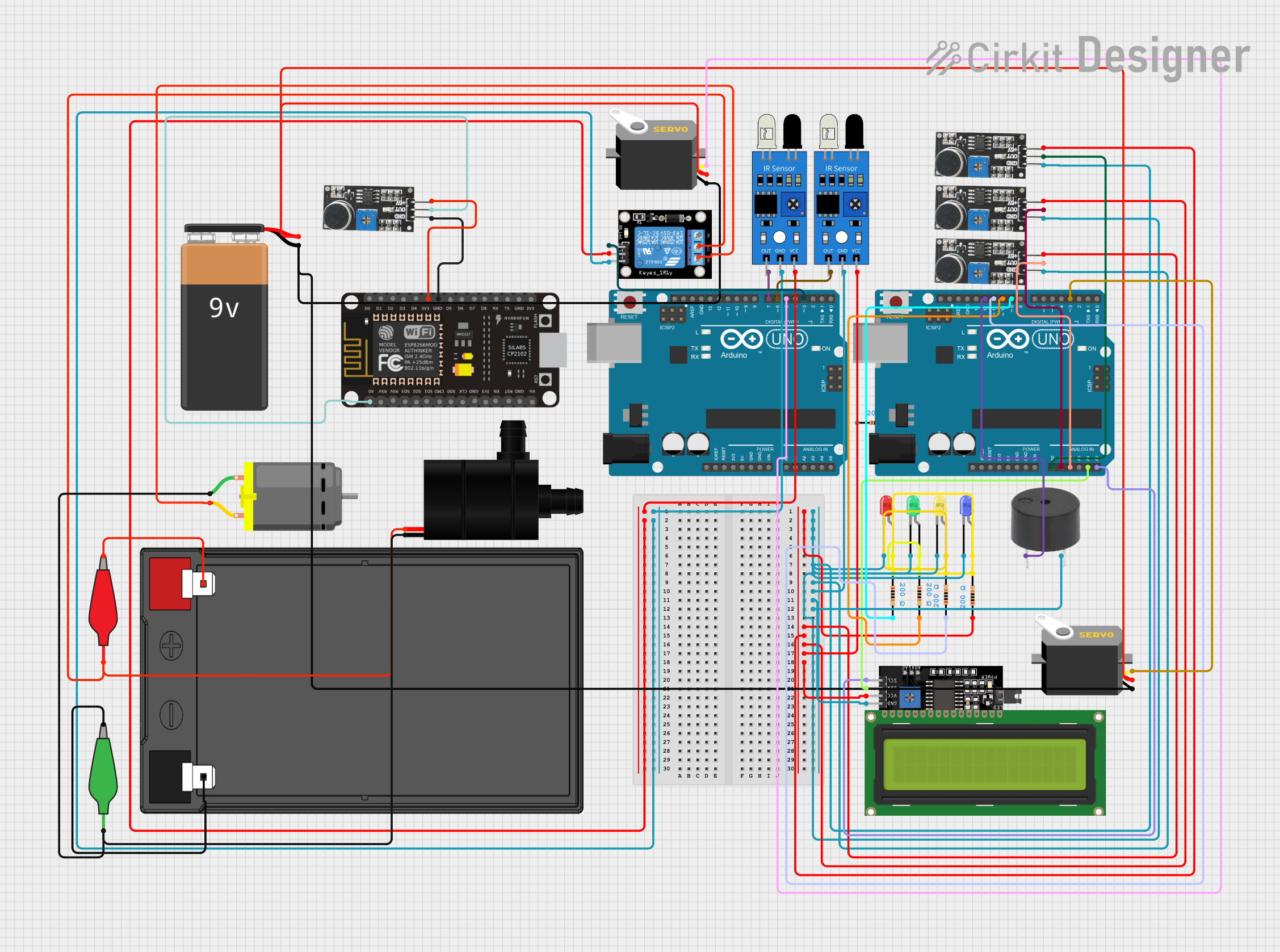
Circuit Documentation
Summary
This circuit integrates a variety of components including microcontrollers (Arduino UNO and ESP8266 NodeMCU), sensors (IR sensors and sound sensors), actuators (servos, a relay module, a water pump, and a DC motor), output devices (LEDs and an LCD display), and a buzzer. The circuit is designed to interact with the environment through its sensors, control actuators and display information based on programmed logic. Power is supplied by a 9V battery and a 12V 7Ah battery, with voltage regulation provided by the microcontrollers and relay module.
Component List
Microcontrollers
- Arduino UNO: A microcontroller board based on the ATmega328P, featuring digital and analog I/O pins.
- ESP8266 NodeMCU: A Wi-Fi enabled microcontroller with digital pins and a single analog input.
Sensors
- Sound Sensor: Captures audio levels from the environment and provides an electrical signal as output.
- IR Sensor: Detects infrared light, commonly used for proximity or motion detection.
Actuators
- Servo: A rotary actuator that allows for precise control of angular position.
- KY-019 Relay Module 1 Channel: An electrically operated switch that allows for controlling high power devices.
- Water Pump: A device used to move liquids, powered by a motor.
- DC Motor: An electrical machine that converts electrical energy into mechanical rotation.
Output Devices
- LED (Red, Green, Yellow, Blue): Light Emitting Diodes of various colors used as indicators.
- LCD Display 16x4 I2C: A liquid crystal display capable of showing 4 lines of 16 characters, interfaced via I2C.
Other Components
- Buzzer: An audio signaling device.
- Resistor: A passive two-terminal electrical component that implements electrical resistance as a circuit element.
- 9V Battery: Provides power to the circuit.
- 12V 7Ah Battery: Provides power to the circuit.
- Alligator Clip Cable: Used to connect components or to probe circuits.
Wiring Details
Arduino UNO
- Digital Pin D7 connected to IR sensor output.
- Digital Pin D6 connected to another IR sensor output.
- Digital Pin D5 connected to Servo pulse.
- Digital Pin D3 connected to Relay Module signal.
- Analog Pin A0 connected to Sound Sensor output.
- Analog Pin A1 connected to another Sound Sensor output.
- Analog Pin A2 connected to another Sound Sensor output.
- I2C Pins A4 (SDA) and A5 (SCL) connected to LCD Display.
ESP8266 NodeMCU
- 3V3 Pin connected to Sound Sensor VCC.
- GND Pin connected to Sound Sensor GND.
- Analog Pin A0 connected to Sound Sensor output.
Sound Sensors
- VCC connected to 3.3V or 5V supply (depending on the sensor).
- GND connected to ground.
- OUT connected to microcontroller analog input pins.
IR Sensors
- VCC connected to 5V supply.
- GND connected to ground.
- OUT connected to microcontroller digital input pins.
Servos
- VCC connected to 9V battery positive terminal.
- GND connected to 9V battery negative terminal and ground.
- Pulse connected to microcontroller digital output pins.
KY-019 Relay Module 1 Channel
- 5V and GND connected to power supply.
- Signal (S) connected to microcontroller digital output pin.
- Common (COM) connected to Water Pump VCC.
- Normally Open (NO) connected to DC Motor pin 2.
LEDs
- Cathodes connected to ground.
- Anodes connected to microcontroller digital output pins through resistors.
LCD Display 16x4 I2C
- SDA and SCL connected to microcontroller I2C pins.
- VCC connected to 5V supply.
- GND connected to ground.
Buzzer
- PIN connected to microcontroller digital output pin.
- GND connected to ground.
Water Pump and DC Motor
- Water Pump VCC connected to Relay Module COM.
- DC Motor pin 2 connected to Relay Module NO.
- Water Pump GND and DC Motor pin 1 connected to 12V 7Ah battery negative terminal via alligator clip cable.
Documented Code
Arduino UNO Code (Instance ID: 5af28f23-e864-4e72-b15d-1f3226375a13)
void setup() {
  // put your setup code here, to run once:

}

void loop() {
  // put your main code here, to run repeatedly:

}
ESP8266 NodeMCU Code (Instance ID: c607c50a-dddd-4bef-baec-8ba2e37ab3ec)
void setup() {
  // put your setup code here, to run once:

}

void loop() {
  // put your main code here, to run repeatedly:

}
Note: The provided code for both microcontrollers is a template with empty setup and loop functions. The actual logic for interacting with the sensors, actuators, and output devices needs to be implemented within these functions.