
Circuit Documentation
Summary of the Circuit
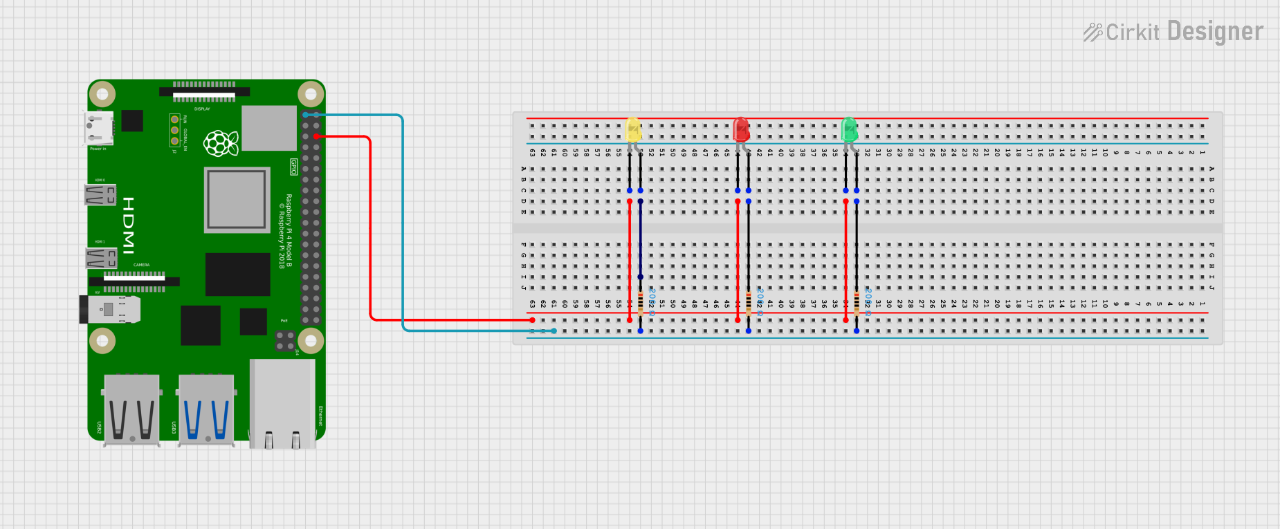
This circuit appears to be a simple LED array controlled by a Raspberry Pi 4B. There are three LEDs of different colors (red, yellow, and green) each connected to a resistor in series. The common cathodes of the LEDs are connected to the ground (GND) of the Raspberry Pi, while the anodes are connected through individual resistors to the 3.3V power supply from the Raspberry Pi. This configuration ensures that each LED has a current-limiting resistor to prevent damage to the LEDs.
Component List
Raspberry Pi 4B
- Description: A single-board computer with multiple GPIO pins.
- Pins: 3V3, 5V, multiple GPIOs, GND, and others.
- Purpose: Acts as the controller for the LED array.
LED: Two Pin (red)
- Description: A basic red LED with an anode and cathode.
- Pins: cathode, anode.
LED: Two Pin (yellow)
- Description: A basic yellow LED with an anode and cathode.
- Pins: cathode, anode.
LED: Two Pin (green)
- Description: A basic green LED with an anode and cathode.
- Pins: cathode, anode.
Resistor (200 Ohms)
- Description: A resistor with a resistance of 200 Ohms.
- Pins: pin1, pin2.
- Properties: Resistance: 200 Ohms.
Wiring Details
Raspberry Pi 4B
- GND connected to:
- Cathode of the red LED
- Cathode of the yellow LED
- Cathode of the green LED
- 3V3 connected to:
- Pin2 of all three 200 Ohm resistors
LED: Two Pin (red)
- Cathode connected to Raspberry Pi 4B GND.
- Anode connected to one end (pin1) of a 200 Ohm resistor.
LED: Two Pin (yellow)
- Cathode connected to Raspberry Pi 4B GND.
- Anode connected to one end (pin1) of a 200 Ohm resistor.
LED: Two Pin (green)
- Cathode connected to Raspberry Pi 4B GND.
- Anode connected to one end (pin1) of a 200 Ohm resistor.
Resistor (200 Ohms)
- Pin1 connected to the anode of a corresponding LED.
- Pin2 connected to the 3V3 pin of the Raspberry Pi 4B.
Documented Code
No code has been provided for the microcontrollers in the circuit. The Raspberry Pi 4B would typically be programmed to control the GPIO pins to which the LEDs are connected, potentially allowing for the LEDs to be turned on or off programmatically. However, without the code, we cannot document the behavior or functionality that has been implemented for this circuit.