
Arduino Mega 2560-Based Smart Weighing System with Bluetooth Connectivity
View and Edit Project In Cirkit Designer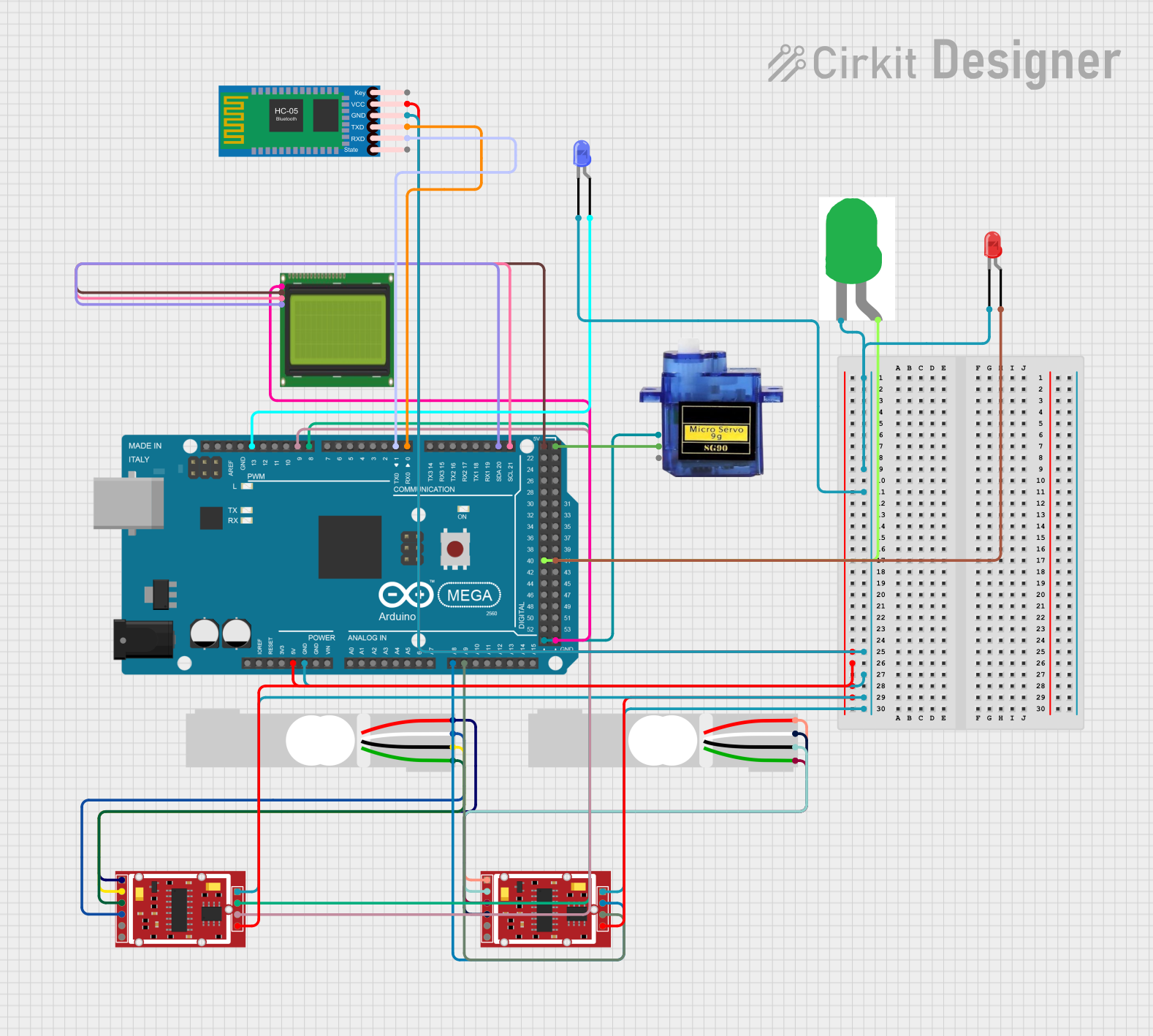
Circuit Documentation
Summary
This circuit involves multiple components including load cells, HX711 weighing sensor modules, an Arduino Mega 2560, a micro servo, an LCD display, LEDs, and an HC-05 Bluetooth module. The circuit is designed to measure weight using load cells, display the data on an LCD, and communicate via Bluetooth. Additionally, it includes LEDs for status indication and a micro servo for mechanical actuation.
Component List
Load Cell - Red/white/black/green
- Pins: E+, A-, E-, A+
- Description: A load cell used for measuring weight.
- Purpose: Converts mechanical force into an electrical signal.
HX711 Weighing Sensor Module
- Pins: B-, B+, A-, A+, E-, E+, VCC, CK/TX, DO/RX, GND
- Description: A precision 24-bit analog-to-digital converter (ADC) designed for weigh scales.
- Purpose: Amplifies and converts the signal from the load cell to a digital value.
Arduino Mega 2560
- Pins: IOREF, RESET, 3V3, 5V, GND, VIN, A0-A15, D0-D53, PWM, AREF, SDA, SCL
- Description: A microcontroller board based on the ATmega2560.
- Purpose: Acts as the main controller for the circuit, processing data and controlling other components.
Micro Servo 9G
- Pins: GND, +5V, PWM
- Description: A small servo motor.
- Purpose: Provides mechanical actuation.
LCD 20x4 I2C
- Pins: GND, 5V, SCA, SCL
- Description: A 20x4 character LCD display with I2C interface.
- Purpose: Displays data.
LED: Two Pin (red)
- Pins: Cathode, Anode
- Description: A red LED.
- Purpose: Status indication.
LED: Two Pin (green)
- Pins: Cathode, Anode
- Description: A green LED.
- Purpose: Status indication.
LED: Two Pin (blue)
- Pins: Cathode, Anode
- Description: A blue LED.
- Purpose: Status indication.
HC-05 Bluetooth Module
- Pins: Key, VCC, GND, TXD, RXD, State
- Description: A Bluetooth module for wireless communication.
- Purpose: Enables Bluetooth communication.
Wiring Details
Load Cell - Red/white/black/green
- E+ connected to E+ of HX711 Weighing Sensor Module
- A- connected to A- of HX711 Weighing Sensor Module
- E- connected to E- of HX711 Weighing Sensor Module
- A+ connected to A+ of HX711 Weighing Sensor Module
HX711 Weighing Sensor Module
- E+ connected to E+ of Load Cell
- A- connected to A- of Load Cell
- E- connected to E- of Load Cell
- A+ connected to A+ of Load Cell
- VCC connected to 5V of Arduino Mega 2560 and VCC of HC-05 Bluetooth Module
- CK/TX connected to D9 PWM of Arduino Mega 2560
- DO/RX connected to D8 PWM of Arduino Mega 2560
- GND connected to GND of Arduino Mega 2560, GND of HC-05 Bluetooth Module, and cathode of LEDs
Arduino Mega 2560
- 5V connected to VCC of HX711 Weighing Sensor Module, VCC of HC-05 Bluetooth Module, and 5V of LCD 20x4 I2C
- GND connected to GND of HX711 Weighing Sensor Module, GND of HC-05 Bluetooth Module, GND of LCD 20x4 I2C, and GND of Micro Servo 9G
- D9 PWM connected to CK/TX of HX711 Weighing Sensor Module
- D8 PWM connected to DO/RX of HX711 Weighing Sensor Module
- A9 connected to CK/TX of second HX711 Weighing Sensor Module
- A8 connected to DO/RX of second HX711 Weighing Sensor Module
- D21/SCL connected to SCL of LCD 20x4 I2C
- D20/SDA connected to SCA of LCD 20x4 I2C
- D0 RX0 connected to TXD of HC-05 Bluetooth Module
- D1 TX0 connected to RXD of HC-05 Bluetooth Module
- D13 PWM connected to anode of blue LED
- D40 connected to anode of green LED
- D41 connected to anode of red LED
- 5V connected to +5V of Micro Servo 9G
Micro Servo 9G
- GND connected to GND of Arduino Mega 2560
- +5V connected to 5V of Arduino Mega 2560
LCD 20x4 I2C
- SCL connected to D21/SCL of Arduino Mega 2560
- SCA connected to D20/SDA of Arduino Mega 2560
- 5V connected to 5V of Arduino Mega 2560
- GND connected to GND of Arduino Mega 2560
LED: Two Pin (red)
- cathode connected to GND of Arduino Mega 2560
- anode connected to D41 of Arduino Mega 2560
LED: Two Pin (green)
- cathode connected to GND of Arduino Mega 2560
- anode connected to D40 of Arduino Mega 2560
LED: Two Pin (blue)
- cathode connected to GND of Arduino Mega 2560
- anode connected to D13 PWM of Arduino Mega 2560
HC-05 Bluetooth Module
- VCC connected to 5V of Arduino Mega 2560
- GND connected to GND of Arduino Mega 2560
- TXD connected to D0 RX0 of Arduino Mega 2560
- RXD connected to D1 TX0 of Arduino Mega 2560
Documented Code
Arduino Mega 2560 Code
void setup() {
  // put your setup code here, to run once:

}

void loop() {
  // put your main code here, to run repeatedly:

}
This code is a basic template for the Arduino Mega 2560. The setup() function is used to initialize any settings or configurations, and the loop() function contains the main code that runs repeatedly. You can add your specific logic for handling the load cells, displaying data on the LCD, controlling the servo, and communicating via Bluetooth in these functions.