Arduino UNO Controlled Robotic System with Ultrasonic Sensing and Servo Actuation
Circuit Documentation
Summary of the Circuit
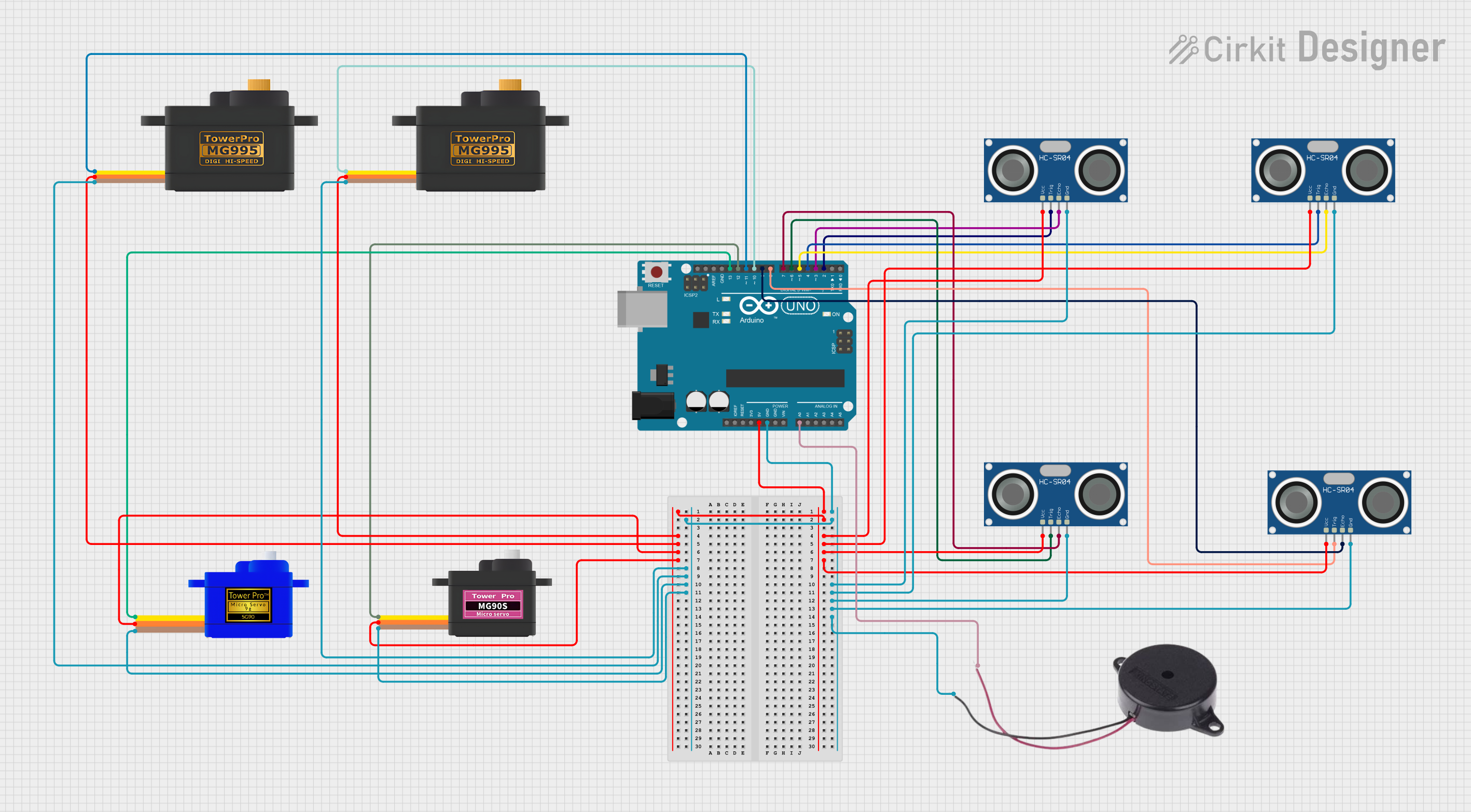
This circuit is designed around the Arduino UNO microcontroller, which serves as the central processing unit. The circuit includes multiple peripheral components, such as HC-SR04 Ultrasonic Sensors for distance measurement, Servomotors (MG995, MG90S, and SG90) for actuation, and a Buzzer for audio signaling. The Arduino UNO is responsible for controlling these components, reading sensor data, and driving the servomotors based on programmed logic. The power for the sensors and servomotors is supplied by the Arduino's 5V output, and all components share a common ground.
Component List
Arduino UNO
- Microcontroller board based on the ATmega328P
- Features digital I/O pins, analog input pins, and power pins
HC-SR04 Ultrasonic Sensor
- Ultrasonic distance measuring module
- Consists of VCC, TRIG, ECHO, and GND pins
Servomotor MG995
- High-torque metal gear servo
- Features SIG (signal), VCC, and GND pins
Servomotor MG90S
- Metal gear micro servo
- Features SIG (signal), VCC, and GND pins
Servomotor SG90
- Micro servo motor
- Features SIG (signal), VCC, and GND pins
Buzzer
- An audio signaling device
- Has POSITIVE and NEGATIVE pins for operation
Wiring Details
Arduino UNO
- 5V: Powers all VCC pins of the servomotors and ultrasonic sensors
- GND: Common ground for all components
- A0: Connected to the POSITIVE pin of the Buzzer
- D2-D13: Control signals for servomotors and communication with ultrasonic sensors
HC-SR04 Ultrasonic Sensors
- VCC: Connected to 5V from Arduino UNO
- TRIG: Connected to digital pins D2, D4, D6, D8 on Arduino UNO for triggering distance measurement
- ECHO: Connected to digital pins D3, D5, D7, D9 on Arduino UNO for receiving distance measurement
- GND: Common ground with Arduino UNO
Servomotors (MG995, MG90S, SG90)
- SIG: Connected to digital pins D10, D11, D12, D13 on Arduino UNO for control signals
- VCC: Powered by 5V from Arduino UNO
- GND: Common ground with Arduino UNO
Buzzer
- POSITIVE: Connected to analog pin A0 on Arduino UNO
- NEGATIVE: Common ground with Arduino UNO
Documented Code
void setup() {
  // put your setup code here, to run once:

}

void loop() {
  // put your main code here, to run repeatedly:

}
The provided code is a template with empty setup() and loop() functions, which are the standard structure for Arduino sketches. The setup() function is intended for initialization code that runs once when the program starts, such as configuring pin modes. The loop() function contains the main logic of the program, which runs continuously after the setup() is complete. The actual implementation details need to be filled in based on the specific requirements of the circuit's operation.