Arduino-Controlled Robotics Interface with Stepper Motor and Multiple Ultrasonic Sensors
Circuit Documentation
Summary
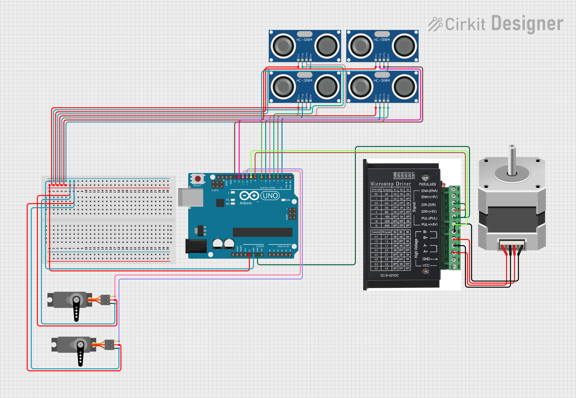
This circuit is designed to control a bipolar stepper motor using a stepper driver, interfaced with an Arduino UNO microcontroller. The circuit also includes multiple HC-SR04 ultrasonic sensors and servo motors, which are likely used for distance measurement and precise angular positioning, respectively. The Arduino UNO provides the control signals for the stepper driver, ultrasonic sensors, and servos.
Component List
Stepper Motor (Bipolar)
- Description: A bipolar stepper motor which requires a stepper driver to operate.
- Pins: D, B, C, A
STEPPER DRIVER
- Description: A driver module to control the bipolar stepper motor.
- Pins: ENA -, ENA +, DIR -, DIR+, PUL -, PUL +, B-, B+, A-, A+, GND, VCC
Arduino UNO
- Description: A microcontroller board based on the ATmega328P, used for controlling the various components in the circuit.
- Pins: UNUSED, IOREF, Reset, 3.3V, 5V, GND, Vin, A0, A1, A2, A3, A4, A5, SCL, SDA, AREF, D13, D12, D11, D10, D9, D8, D7, D6, D5, D4, D3, D2, D1, D0
HC-SR04 Ultrasonic Sensor
- Description: An ultrasonic distance sensor that uses sonar to determine the distance to an object.
- Pins: VCC, TRIG, ECHO, GND
Servo
- Description: A rotary actuator or linear actuator that allows for precise control of angular or linear position.
- Pins: GND, VCC, PWM
Wiring Details
Stepper Motor (Bipolar)
- D: Connected to STEPPER DRIVER B-
- B: Connected to STEPPER DRIVER B+
- C: Connected to STEPPER DRIVER A-
- A: Connected to STEPPER DRIVER A+
STEPPER DRIVER
- ENA -/+: Not connected in the provided net list.
- DIR -: Connected to Arduino UNO GND
- DIR+: Connected to Arduino UNO D8
- PUL -: Connected to Arduino UNO GND
- PUL +: Connected to Arduino UNO D9
- B-: Connected to Stepper Motor D
- B+: Connected to Stepper Motor B
- A-: Connected to Stepper Motor C
- A+: Connected to Stepper Motor A
- GND: Connected to Arduino UNO GND
- VCC: Not connected in the provided net list.
Arduino UNO
- 5V: Powers all HC-SR04 Ultrasonic Sensors and Servos VCC pins.
- GND: Common ground for STEPPER DRIVER, all HC-SR04 Ultrasonic Sensors, and Servos.
- D13: Connected to HC-SR04 Ultrasonic Sensor ECHO.
- D12: Connected to HC-SR04 Ultrasonic Sensor TRIG.
- D11: Connected to Servo PWM.
- D10: Connected to Servo PWM.
- D9: Connected to STEPPER DRIVER PUL +.
- D8: Connected to STEPPER DRIVER DIR+.
- D7: Connected to HC-SR04 Ultrasonic Sensor ECHO.
- D6: Connected to HC-SR04 Ultrasonic Sensor TRIG.
- D5: Connected to HC-SR04 Ultrasonic Sensor ECHO.
- D4: Connected to HC-SR04 Ultrasonic Sensor TRIG.
- D3: Connected to HC-SR04 Ultrasonic Sensor ECHO.
- D2: Connected to HC-SR04 Ultrasonic Sensor TRIG.
HC-SR04 Ultrasonic Sensors
- VCC: Powered by Arduino UNO 5V.
- TRIG: Connected to Arduino UNO digital pins (D2, D4, D6, D12).
- ECHO: Connected to Arduino UNO digital pins (D3, D5, D7, D13).
- GND: Common ground with Arduino UNO.
Servos
- GND: Common ground with Arduino UNO.
- VCC: Powered by Arduino UNO 5V.
- PWM: Controlled by Arduino UNO digital pins (D10, D11).
Documented Code
void setup() {
  // put your setup code here, to run once:

}

void loop() {
  // put your main code here, to run repeatedly:

}
The provided code is a template with empty setup() and loop() functions, which are the standard structure for Arduino sketches. The setup() function is intended to contain initialization code that runs once when the microcontroller is powered on or reset. The loop() function is intended to contain the main logic of the program, which runs repeatedly as long as the microcontroller is powered. Additional code is required to control the stepper motor, read the ultrasonic sensors, and drive the servo motors based on the specific application requirements.