Cirkit Designer
Your all-in-one circuit design IDE
Home /
Project Documentation
Arduino UNO Controlled Time-Displaying System with Pushbutton Interaction and Status LEDs
Circuit Documentation
Summary
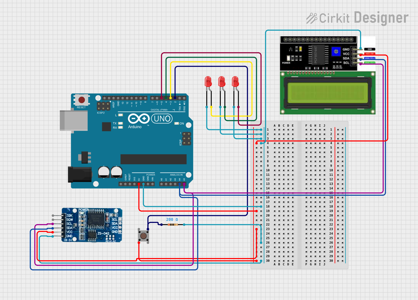
The circuit in question appears to be a microcontroller-based system designed to interface with an LCD I2C display, an RTC (Real-Time Clock) module, and multiple LEDs. The Arduino UNO serves as the central processing unit, controlling the LEDs and communicating with the RTC and LCD via I2C protocol. A pushbutton is included, likely for user input, and a resistor is present, possibly for current limiting purposes.
Component List
Pushbutton
- Description: A standard pushbutton with four pins, typically used for user input.
- Pins: Pin 3 (out), Pin 4 (out), Pin 1 (in), Pin 2 (in)
Resistor
- Description: A passive two-terminal electrical component that implements electrical resistance as a circuit element.
- Value: 200 Ohms
Arduino UNO
- Description: A microcontroller board based on the ATmega328P, widely used for building digital devices and interactive objects that can sense and control objects in the physical and digital world.
- Pins: UNUSED, IOREF, Reset, 3.3V, 5V, GND, Vin, A0-A5, SCL, SDA, AREF, D0-D13
RTC DS3231
- Description: A highly accurate I2C real-time clock (RTC) with an integrated temperature-compensated crystal oscillator (TCXO) and crystal.
- Pins: 32K, SQW, SCL, SDA, VCC, GND
LED: Two Pin (red)
- Description: A basic red light-emitting diode with two pins, an anode, and a cathode for emitting red light when forward-biased.
- Pins: cathode, anode
LCD I2C Display
- Description: A liquid crystal display that uses the I2C bus for communication, commonly used for displaying data in electronic devices.
- Pins: GND, VCC, SDA, SCL
Wiring Details
Pushbutton
- Pin 2 (in) connected to 5V from Arduino UNO
- Pin 3 (out) connected to D2 on Arduino UNO through a 200 Ohm resistor
Resistor
- pin1 connected to D2 on Arduino UNO
- pin2 connected to GND net
Arduino UNO
- 5V supplying power to VCC net
- GND connected to GND net
- D2 connected to Pushbutton and Resistor
- D3 connected to anode of one LED
- D4 connected to anode of another LED
- D5 connected to anode of the third LED
- A4 (SDA) connected to SDA line of I2C bus
- A5 (SCL) connected to SCL line of I2C bus
RTC DS3231
- VCC connected to 5V from Arduino UNO
- GND connected to GND net
- SCL connected to A5 (SCL) on Arduino UNO
- SDA connected to A4 (SDA) on Arduino UNO
LEDs
- cathode of all LEDs connected to GND net
- anode of each LED connected to a separate digital pin (D3, D4, D5) on Arduino UNO
LCD I2C Display
- GND connected to GND net
- VCC connected to 5V from Arduino UNO
- SDA connected to A4 (SDA) on Arduino UNO
- SCL connected to A5 (SCL) on Arduino UNO
Documented Code
Arduino UNO Code (sketch.ino)
void setup() {
  // put your setup code here, to run once:

}

void loop() {
  // put your main code here, to run repeatedly:

}
Note: The provided code is a template and does not contain any functional code. It needs to be populated with instructions to control the LEDs, read the pushbutton state, and communicate with the RTC and LCD.
Additional Files
- documentation.txt: This file is mentioned but no content was provided. It is likely intended for additional notes or manual documentation.