Cirkit Designer
Your all-in-one circuit design IDE
Home /
Project Documentation
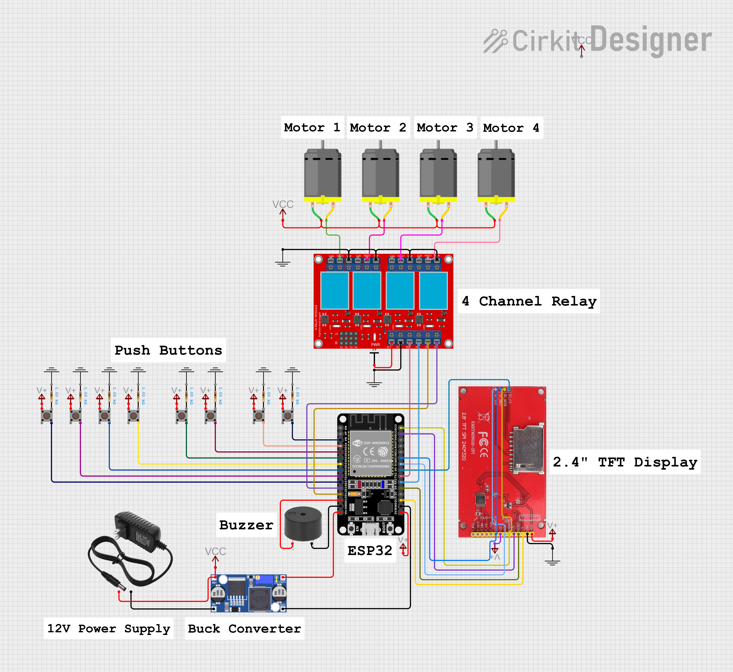
ESP32-Controlled Multi-Input Relay with TFT Display and Buzzer Notification System

Circuit Documentation
Summary
This circuit is designed around the ESP32 microcontroller, which interfaces with a variety of components including a buzzer, multiple pushbuttons, an ILI9341 TFT display, a 4-channel relay module, and several DC motors. The circuit is powered by a 12V power supply, which is stepped down to the required voltages for the ESP32 and other components using a buck converter. The pushbuttons are used as inputs to the ESP32, which controls the buzzer, the display, and the relay module that in turn controls the DC motors.
Component List
Microcontroller
- ESP32 (30 pin): A microcontroller with a wide range of GPIO pins for interfacing with various components.
Input Devices
- Pushbuttons: Multiple instances of pushbuttons used to provide input signals to the ESP32.
Output Devices
- Buzzer: An audible signaling device controlled by the ESP32.
- ILI9341 TFT display: A color graphic display for visual output, interfaced with the ESP32.
- 4 channel relay module: Used to control higher power devices like DC motors.
- DC Motors: Actuators that are controlled via the relay module.
Power Supply and Management
- 12v power supply: Provides the main power source for the circuit.
- Buck converter: Steps down the voltage from the 12V power supply to a lower voltage suitable for the ESP32 and other components.
- VIN components: Represent voltage input lines to various components.
Passive Components
- Resistors: Used for current limiting or voltage division in the circuit.
Grounding
- GND components: Represent ground connections in the circuit.
Wiring Details
ESP32 (30 pin)
- GPIO D13 connected to Buzzer PIN
- GND connected to Buzzer GND and Buck converter OUT-
- VN connected to Pushbutton Pin 4 (out)
- GPIOs D34, D35, D32, D33, D25, D26, D27 connected to corresponding Pushbutton Pin 4 (out)
- GPIO D14, D12 connected to 4 channel relay module IN 4, IN 3
- Vin connected to Buck converter OUT+
- GPIO D23, D22, D19, D18, D5, TX2, RX2, D4, D15 connected to ILI9341 TFT display corresponding pins
- 3V3 connected to VIN VCC
Pushbuttons
- Pin 1 (in) connected to VIN VCC
- Pin 4 (out) connected to corresponding ESP32 GPIOs
Buzzer
- PIN connected to ESP32 GPIO D13
- GND connected to ESP32 GND
ILI9341 TFT display
- SD_MOSI, SD(MOSI), D/C, SDO(MISO), SD_MISO, SCK, SD_SCK, SD_CS, RESET, CS, LED connected to corresponding ESP32 GPIOs
- VCC connected to VIN VCC
- GND connected to GND
4 channel relay module
- IN 4, IN 3, IN 1, IN 2 connected to corresponding ESP32 GPIOs
- N.O. 4, N.O. 3, N.O. 2, N.O. 1 connected to GND
- COM 4, COM 3, COM 2, COM 1 connected to corresponding DC Motor pin 2
- VCC+ connected to Vcc Vcc
- VCC- (GND) connected to GND
DC Motors
- pin 1 of all DC Motors connected to VCC 12V VCC 12
Power Supply and Management
- 12v power supply + connected to VCC 12V VCC 12 and Buck converter IN+
- 12v power supply - connected to Buck converter IN-
- Buck converter OUT+ connected to ESP32 Vin
- Buck converter OUT- connected to ESP32 GND
Documented Code
sketch.ino
void setup() {
  // put your setup code here, to run once:

}

void loop() {
  // put your main code here, to run repeatedly:

}
documentation.txt
(No additional documentation provided for the code)
(Note: The code provided is a template and does not contain any functional code for controlling the circuit components. Additional programming will be required to achieve the desired functionality.)