
Arduino Nano-Based Motion-Activated Peristaltic Pump with LED Indicators
View and Edit Project In Cirkit Designer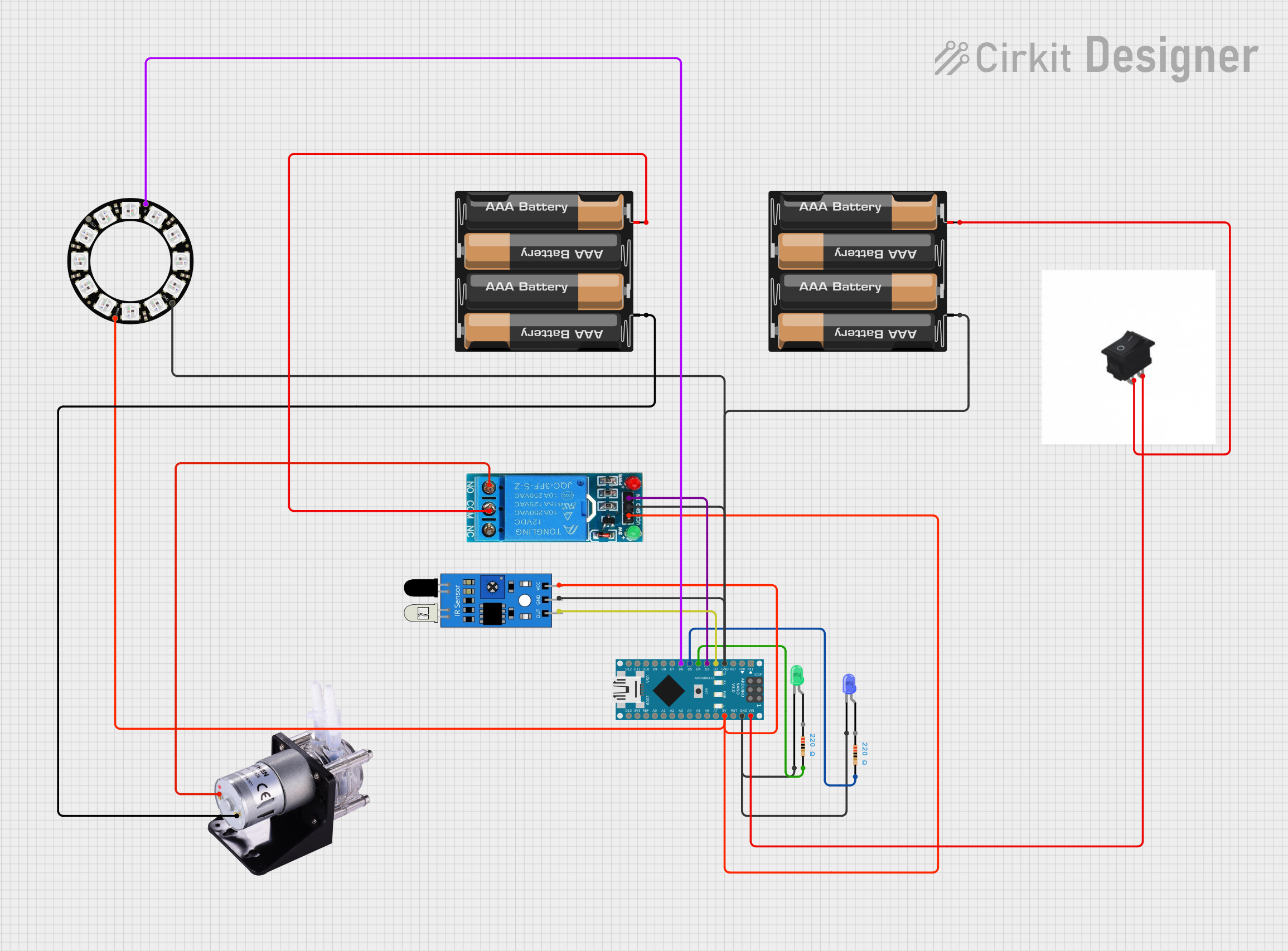
Circuit Documentation
Summary
This circuit is designed to control a peristaltic pump using an Arduino Nano, an IR sensor, and a relay. The circuit also includes an LED ring and two individual LEDs (green and blue) for visual feedback. The IR sensor detects motion, and based on its state, the Arduino controls the relay to turn the pump on or off. The LED ring and blue LED provide visual indications when the pump is activated.
Component List
Arduino Nano
- Description: Microcontroller board based on the ATmega328P.
- Pins: D1/TX, D0/RX, RESET, GND, D2, D3, D4, D5, D6, D7, D8, D9, D10, D11/MOSI, D12/MISO, VIN, 5V, A7, A6, A5, A4, A3, A2, A1, A0, AREF, 3V3, D13/SCK
IR Sensor
- Description: Infrared sensor for motion detection.
- Pins: out, gnd, vcc
12V Single Channel Relay
- Description: Relay module for switching high-power devices.
- Pins: NC, COM, NO, IN, GND, VCC
LED: Two Pin (Green)
- Description: Green LED for visual indication.
- Pins: cathode, anode
Resistor (220 Ohms)
- Description: Resistor to limit current.
- Pins: pin1, pin2
LED: Two Pin (Blue)
- Description: Blue LED for visual indication.
- Pins: cathode, anode
Peristaltic Pump
- Description: Pump for fluid transfer.
- Pins: +, -
Rocker Switch
- Description: Switch to control power.
- Pins: 1, 2
4 x AAA Battery Mount
- Description: Battery holder for 4 AAA batteries.
- Pins: -, +
Adafruit 12 NeoPixel Ring
- Description: LED ring with 12 NeoPixels.
- Pins: OUT, VDD, IN, GND
Wiring Details
Arduino Nano
- GND: Connected to GND of IR sensor, relay, NeoPixel ring, blue LED, green LED, and one battery mount.
- D2: Connected to
outpin of IR sensor. - D3: Connected to
INpin of relay. - D4: Connected to
pin2of one 220 Ohm resistor. - D5: Connected to
pin2of another 220 Ohm resistor. - D6: Connected to
INpin of NeoPixel ring. - VIN: Connected to pin 1 of rocker switch.
- 5V: Connected to VCC of IR sensor, relay, NeoPixel ring.
IR Sensor
- gnd: Connected to GND of Arduino Nano.
- out: Connected to D2 of Arduino Nano.
- vcc: Connected to 5V of Arduino Nano.
12V Single Channel Relay
- GND: Connected to GND of Arduino Nano.
- IN: Connected to D3 of Arduino Nano.
- VCC: Connected to 5V of Arduino Nano.
- COM: Connected to + of one battery mount.
- NO: Connected to + of peristaltic pump.
LED: Two Pin (Green)
- cathode: Connected to GND of Arduino Nano.
- anode: Connected to
pin1of one 220 Ohm resistor.
Resistor (220 Ohms)
- pin1: Connected to anode of green LED.
- pin2: Connected to D4 of Arduino Nano.
LED: Two Pin (Blue)
- cathode: Connected to GND of Arduino Nano.
- anode: Connected to
pin1of another 220 Ohm resistor.
Resistor (220 Ohms)
- pin1: Connected to anode of blue LED.
- pin2: Connected to D5 of Arduino Nano.
Peristaltic Pump
- +: Connected to NO of relay.
- -: Connected to - of one battery mount.
Rocker Switch
- 1: Connected to VIN of Arduino Nano.
- 2: Connected to + of another battery mount.
4 x AAA Battery Mount
- -: Connected to GND of Arduino Nano.
- +: Connected to COM of relay.
Adafruit 12 NeoPixel Ring
- GND: Connected to GND of Arduino Nano.
- IN: Connected to D6 of Arduino Nano.
- VDD: Connected to 5V of Arduino Nano.
Code Documentation
#include <Adafruit_NeoPixel.h>

#define LED_RING_PIN 6      // Pin connected to the LED ring data input
#define NUM_LEDS 12         // Number of LEDs on the ring (adjust as per your LED ring)
const int irSensorPin = 2;  // Pin connected to the IR sensor
const int relayPin = 3;     // Pin connected to the relay
const int greenLedPin = 4;  // Pin connected to the green LED (always on)
const int blueLedPin = 5;   // Pin connected to the blue LED

int sensorState = 0;        // Variable to store sensor state

Adafruit_NeoPixel ledRing = Adafruit_NeoPixel(NUM_LEDS, LED_RING_PIN, NEO_GRB + NEO_KHZ800);

void setup() {
  Serial.begin(9600);                // Start serial communication at 9600 baud
  pinMode(irSensorPin, INPUT);       // Set IR sensor as input
  pinMode(relayPin, OUTPUT);         // Set relay as output
  pinMode(greenLedPin, OUTPUT);      // Set green LED as output
  pinMode(blueLedPin, OUTPUT);       // Set blue LED as output
  digitalWrite(greenLedPin, HIGH);   // Turn on green LED (always on)
  digitalWrite(blueLedPin, LOW);     // Initialize blue LED as off
  digitalWrite(relayPin, HIGH);      // Initialize relay to off (pump off by default)
  ledRing.begin();                   // Initialize the LED ring
  ledRing.show();                    // Turn off all LEDs initially
}

void loop() {
  sensorState = digitalRead(irSensorPin);
  Serial.print("Sensor state:");
  Serial.println(sensorState);
  if (sensorState == 1) {            // If sensor does NOT detect motion (HIGH state)
    digitalWrite(relayPin, HIGH);    // Turn off the relay
    turnOffLedRing();                // Turn off the LED ring
  } else {                           // If sensor detects motion (LOW state)
    digitalWrite(relayPin, LOW);     // Turn on the relay
    digitalWrite(blueLedPin, HIGH);  // Turn on blue LED
    lightUpLedRingBlue();            // Light up the LED ring in blue
    delay(500);                      // Keep blue LED on for 0.5 second
    digitalWrite(blueLedPin, LOW);   // Turn off blue LED
    turnOffLedRing();                // Turn off the LED ring
  }
}

void lightUpLedRingBlue() {
  for (int i = 0; i < NUM_LEDS; i++) {
    ledRing.setPixelColor(i, ledRing.Color(0, 0, 255)); // Set LED to blue (R=0, G=0, B=255)
  }
  ledRing.show();
}

void turnOffLedRing() {
  for (int i = 0; i < NUM_LEDS; i++) {
    ledRing.setPixelColor(i, ledRing.Color(0, 0, 0)); // Turn off LED
  }
  ledRing.show();
}
This code initializes the IR sensor, relay, green LED, blue LED, and NeoPixel ring. The main loop reads the state of the IR sensor and controls the relay and LEDs accordingly. When motion is detected, the relay is activated to turn on the pump, and the blue LED and NeoPixel ring are lit up.