
Arduino-Based Environmental Monitoring System with LCD Display
View and Edit Project In Cirkit Designer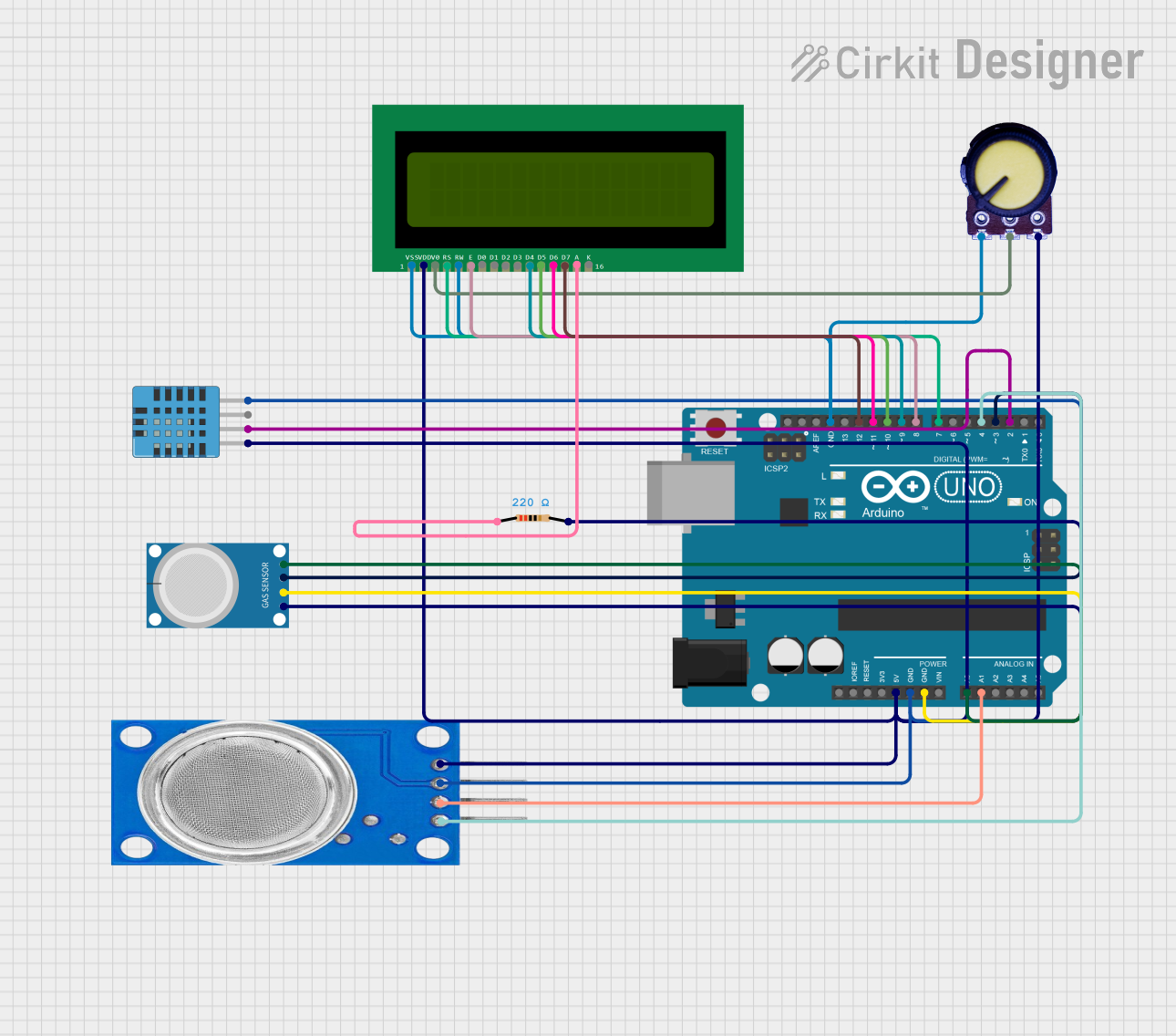
Circuit Documentation
Summary
This circuit integrates various sensors and a display module with an Arduino UNO microcontroller. The sensors include a DHT11 Humidity and Temperature Sensor, MQ-4 and MQ135 gas sensors, and a potentiometer. The data from these sensors is displayed on a 16x2 LCD screen. The circuit is powered by the Arduino UNO, which also handles the data processing and display logic.
Component List
DHT11 Humidity and Temperature Sensor
- Pins: VDD, DATA, NULL, GND
- Description: Measures humidity and temperature.
- Purpose in Circuit: Provides humidity and temperature data to the Arduino.
MQ-4 Gas Sensor
- Pins: A0, D0, GND, VCC
- Description: Detects methane gas.
- Purpose in Circuit: Provides analog and digital signals to the Arduino based on methane concentration.
MQ135 Gas Sensor
- Pins: VCC, GND, A0, D0
- Description: Detects air quality.
- Purpose in Circuit: Provides analog and digital signals to the Arduino based on air quality.
16x2 LCD
- Pins: VSS, VDD, V0, RS, RW, E, D1, D0, D2, D3, D4, D6, D5, D7, A, K
- Description: Displays data.
- Purpose in Circuit: Displays sensor data and other information.
Arduino UNO
- Pins: UNUSED, IOREF, Reset, 3.3V, 5V, GND, Vin, A0, A1, A2, A3, A4, A5, SCL, SDA, AREF, D13, D12, D11, D10, D9, D8, D7, D6, D5, D4, D3, D2, D1, D0
- Description: Microcontroller board.
- Purpose in Circuit: Central processing unit for the circuit.
Potentiometer
- Pins: GND, Output, VCC
- Description: Variable resistor.
- Purpose in Circuit: Adjusts the contrast of the LCD.
Resistor
- Pins: pin1, pin2
- Description: 220 Ohms resistor.
- Purpose in Circuit: Current limiting resistor for the LCD backlight.
Wiring Details
DHT11 Humidity and Temperature Sensor
- VDD connected to 5V on Arduino UNO.
- DATA connected to D2 on Arduino UNO.
- GND connected to GND on Arduino UNO.
MQ-4 Gas Sensor
- VCC connected to 5V on Arduino UNO.
- A0 connected to A0 on Arduino UNO.
- D0 connected to D3 on Arduino UNO.
- GND connected to GND on Arduino UNO.
MQ135 Gas Sensor
- VCC connected to 5V on Arduino UNO.
- A0 connected to A1 on Arduino UNO.
- D0 connected to D4 on Arduino UNO.
- GND connected to GND on Arduino UNO.
16x2 LCD
- VDD connected to 5V on Arduino UNO.
- VSS connected to GND on Arduino UNO.
- V0 connected to Output on Potentiometer.
- RS connected to D7 on Arduino UNO.
- RW connected to GND on Arduino UNO.
- E connected to D8 on Arduino UNO.
- D4 connected to D9 on Arduino UNO.
- D5 connected to D10 on Arduino UNO.
- D6 connected to D11 on Arduino UNO.
- D7 connected to D12 on Arduino UNO.
- A connected to pin1 on Resistor.
- K connected to GND on Arduino UNO.
Arduino UNO
- 5V connected to VDD on DHT11, MQ-4, MQ135, and 16x2 LCD.
- GND connected to GND on DHT11, MQ-4, MQ135, and 16x2 LCD.
- D2 connected to DATA on DHT11.
- A0 connected to A0 on MQ-4.
- D3 connected to D0 on MQ-4.
- A1 connected to A0 on MQ135.
- D4 connected to D0 on MQ135.
- D7 connected to RS on 16x2 LCD.
- D8 connected to E on 16x2 LCD.
- D9 connected to D4 on 16x2 LCD.
- D10 connected to D5 on 16x2 LCD.
- D11 connected to D6 on 16x2 LCD.
- D12 connected to D7 on 16x2 LCD.
Potentiometer
- VCC connected to 5V on Arduino UNO.
- GND connected to GND on Arduino UNO.
- Output connected to V0 on 16x2 LCD.
Resistor
- pin1 connected to A on 16x2 LCD.
- pin2 connected to 5V on Arduino UNO.
Documented Code
Arduino UNO Code
void setup() {
  // put your setup code here, to run once:

}

void loop() {
  // put your main code here, to run repeatedly:

}
This code is a basic template for the Arduino UNO. The setup() function is where you initialize your sensors and display, and the loop() function is where you handle the main logic of reading sensor data and updating the display.