
ESP32-Based Smart Environmental Monitoring System with Wi-Fi and AC Control
View and Edit Project In Cirkit Designer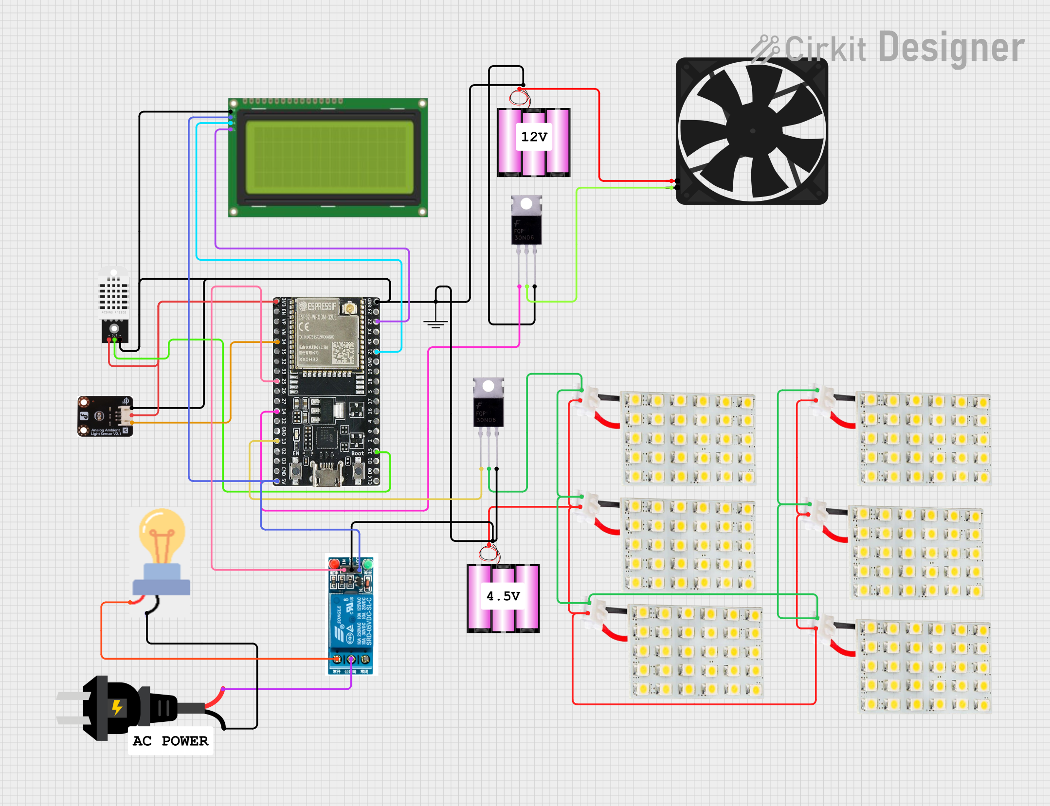
Circuit Documentation
Summary
The circuit in question appears to be a control and monitoring system that utilizes an ESP32-WROOM-32UE microcontroller to interface with various sensors, actuators, and display modules. The system is designed to measure ambient conditions using an ambient light sensor and a DHT22 temperature and humidity sensor. It controls a fan and a bulb through MOSFETs and a relay, respectively. The system status is displayed on an LCD 20x4 I2C module, and multiple LED boards are used for indication purposes. The circuit is powered by 12V batteries.
Component List
Ambient Light Sensor
- Pins: GND, VCC, DATA
- Description: Measures the ambient light intensity.
ESP32-WROOM-32UE
- Pins: 3v3, EN, VP, VN, 34, 35, 32, 33, 25, 26, 27, 14, 12, GND, 13, D2, D3, 5V, 23, 22, TX, RX, 21, 19, 18, 5, 17, 16, 4, 0, 2, 15, D1, D0, CKL
- Description: Microcontroller unit for controlling and interfacing with other components in the circuit.
DHT22
- Pins: VCC, OUT, GND
- Description: Sensor for measuring temperature and humidity.
Fan
- Pins: GND, 5V
- Description: Actuator for air circulation.
MOSFET (x2)
- Pins: Gate, Drain, Source
- Description: Transistor used for switching electronic signals.
Battery 12V (x2)
- Pins: +, -
- Description: Provides power to the circuit.
GND
- Pins: GND
- Description: Common ground reference point for the circuit.
LED Board (x6)
- Pins: VCC, GND
- Description: Used for indication purposes.
LCD 20x4 I2C
- Pins: GND, 5v, SCA, SCL
- Description: Display module for showing system status and readings.
5V Relay
- Pins: Normally Open, Common terminal, Normally Closed, In, GND, VCC
- Description: Electromechanical switch used to control high power devices.
AC Source
- Pins: +, -
- Description: Provides alternating current for the bulb.
Bulb
- Pins: GND, Power
- Description: Lighting device controlled by the relay.
Wiring Details
Ambient Light Sensor
- GND: Connected to system ground.
- VCC: Connected to 3.3V from ESP32.
- DATA: Connected to pin 34 of ESP32.
ESP32-WROOM-32UE
- GND: Connected to system ground.
- 3v3: Provides power to DHT22 and Ambient Light Sensor.
- 5V: Provides power to LCD 20x4 I2C and 5V Relay.
- 34: Receives data from Ambient Light Sensor.
- 25: Controls 5V Relay.
- 14, 13: Control gates of two MOSFETs.
- 22, 21: I2C communication with LCD 20x4 I2C.
- 15: Receives data from DHT22.
DHT22
- GND: Connected to system ground.
- VCC: Connected to 3.3V from ESP32.
- OUT: Connected to pin 15 of ESP32.
Fan
- GND: Connected to Drain of one MOSFET.
- 5V: Connected to + of one 12V Battery.
MOSFETs
- Source (Both): Connected to system ground.
- Gate (Both): Controlled by ESP32 (pins 14 and 13).
- Drain (One): Connected to GND of Fan.
Battery 12V
-
- (Both): One provides power to Fan, the other to LED Boards.
-
- (Both): Connected to system ground.
LED Boards
- VCC (All): Connected to + of one 12V Battery.
- GND (All): Connected to Drain of one MOSFET.
LCD 20x4 I2C
- GND: Connected to system ground.
- 5v: Connected to 5V from ESP32.
- SCA: Connected to pin 21 of ESP32.
- SCL: Connected to pin 22 of ESP32.
5V Relay
- In: Controlled by pin 25 of ESP32.
- VCC: Connected to 5V from ESP32.
- GND: Connected to system ground.
- Normally Open: Connected to power of Bulb.
- Common terminal: Connected to + of AC Source.
AC Source
- +: Connected to Common terminal of 5V Relay.
- -: Connected to GND of Bulb.
Bulb
- GND: Connected to - of AC Source.
- Power: Connected to Normally Open of 5V Relay.
Documented Code
No code was provided for the microcontrollers in the circuit. The documentation of the code would typically include descriptions of the functions, algorithms, and logic used to control the components based on sensor inputs and desired outputs. It would also detail any communication protocols used, such as I2C for the LCD display, and how the microcontroller's GPIO pins are configured and used.