
Circuit Documentation
Summary
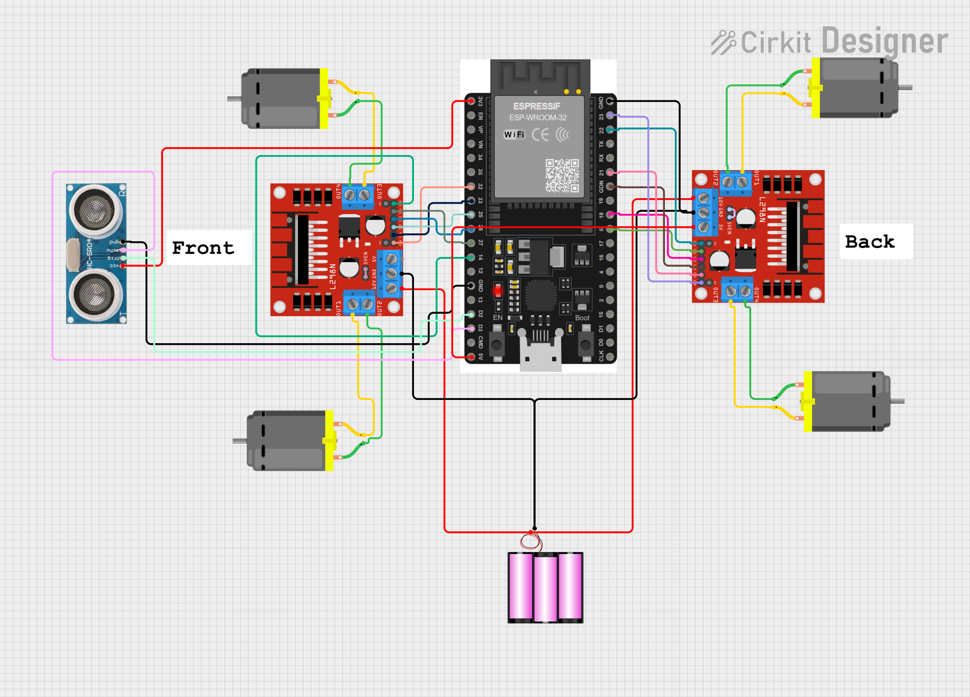
This circuit is designed to control multiple DC motors using an ESP32 microcontroller and two L298N DC motor drivers. It also includes a 12V battery for power and an ultrasonic sensor for distance measurement. The ESP32 is responsible for processing inputs and outputs, controlling the motor drivers, and interfacing with the ultrasonic sensor.
Component List
Microcontroller
- ESP32 38 PINS: A microcontroller with a variety of GPIO pins for interfacing with sensors, motor drivers, and other peripherals.
Motor Drivers
- L298N DC motor driver: Used to control the direction and speed of DC motors. Two instances of this component are used in the circuit to drive multiple motors.
Motors
- DC Motor: Four instances of a generic DC motor are included in the circuit for motion control.
Power Supply
- Battery 12V: Provides the necessary power to the motor drivers and motors.
Sensor
- Ultrasonic Sensor: Measures distances by emitting ultrasonic waves and measuring the time taken for the echo to return.
Comments
- Comment: Placeholder components that may represent annotations or notes in the circuit design.
Wiring Details
ESP32 38 PINS
- GND: Connected to the ground pins of both L298N motor drivers, the ultrasonic sensor, and the negative terminal of the battery.
- 3V3: Powers the ultrasonic sensor.
- 5V/VIN: Provides 5V to one of the L298N motor drivers.
- GPIOs (23, 22/SCL, 21/SDA, 18, 5, 32, 33, 25, 26, 27, 14, D2, D3): Control signals for the motor drivers and the ultrasonic sensor.
L298N DC motor driver (x2)
- GND: Connected to the ESP32 GND and the battery negative terminal.
- 12V: Connected to the positive terminal of the battery.
- 5V: Powered by the ESP32 5V/VIN pin (one instance).
- ENA, ENB, IN1, IN2, IN3, IN4: Control signals received from the ESP32 GPIOs.
- OUT1, OUT2, OUT3, OUT4: Connected to the respective pins of the DC motors.
DC Motor (x4)
- Pin 1 and Pin 2: Connected to the respective OUT pins of the L298N motor drivers.
Battery 12V
- + and -: Powers the motor drivers and through them, the motors.
Ultrasonic Sensor
- +VCC: Powered by the ESP32 3V3 pin.
- GND: Connected to the ESP32 GND.
- Trigger: Controlled by the ESP32 D2 GPIO.
- Echo: Connected to the ESP32 D3 GPIO.
Documented Code
ESP32 Code (sketch.ino)
#include <esp_now.h>
// The library to include was not specified

void setup() {
  // put your setup code here, to run once:

}

void loop() {
  // put your main code here, to run repeatedly:

}
Additional Notes (documentation.txt)
The code provided for the ESP32 is a template and does not contain any functional code. It includes the ESP-NOW library for possible wireless communication but lacks the necessary setup and loop code to control the motors or read from the ultrasonic sensor. Further implementation is required to achieve the desired functionality.