
Dual LED Blinker Circuit with NPN Transistors and Capacitors
View and Edit Project In Cirkit Designer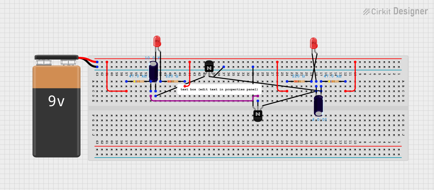
Circuit Documentation
Summary
The circuit in question appears to be a simple LED driver circuit with a 9V power supply. It includes a series of resistors, two NPN transistors, two electrolytic capacitors, and two LEDs. The resistors are used to limit current and set biasing conditions for the transistors. The transistors are likely used as switches or amplifiers. The capacitors may be used for smoothing voltage or as part of a timing circuit. The LEDs are the load, and they emit light when the circuit is powered. There is no microcontroller code provided, indicating that this circuit operates purely on electronic principles without programmable control.
Component List
9V Battery
- Description: Provides the power supply for the circuit.
Resistor (220 Ohms)
- Description: Limits the current to protect components such as LEDs.
Resistor (47k Ohms)
- Description: Typically used for biasing transistors or as a pull-up/pull-down resistor.
LED: Two Pin (red)
- Description: Emits light when forward-biased.
Electrolytic Capacitor (10 Farads)
- Description: Stores electrical energy and can provide smoothing in power supplies.
NPN Transistor (EBC)
- Description: Acts as a switch or amplifier, controlling current flow between collector and emitter based on the base signal.
Comment
- Description: May contain notes or explanations about the circuit, but no specific details are provided.
Wiring Details
9V Battery
- Positive terminal connected to:
- Pin2 of a 47k Ohm resistor
- Pin1 of a 220 Ohm resistor
- Negative terminal connected to:
- Collector of an NPN transistor
Resistor (220 Ohms)
- One pin connected to:
- Anode of an LED
- Other pin connected to:
- Positive terminal of the 9V battery
- Pin2 of another 220 Ohm resistor
Resistor (47k Ohms)
- One pin connected to:
- Base of an NPN transistor
- Negative terminal of an electrolytic capacitor
- Other pin connected to:
- Positive terminal of the 9V battery
LED: Two Pin (red)
- Anode connected to:
- Pin1 of a 220 Ohm resistor
- Cathode connected to:
- Positive terminal of an electrolytic capacitor
- Emitter of an NPN transistor
Electrolytic Capacitor (10 Farads)
- Positive terminal connected to:
- Cathode of an LED
- Negative terminal connected to:
- Base of an NPN transistor
- Pin2 of a 47k Ohm resistor
NPN Transistor (EBC)
- Base connected to:
- Negative terminal of an electrolytic capacitor
- Pin1 of a 47k Ohm resistor
- Emitter connected to:
- Cathode of an LED
- Collector connected to:
- Negative terminal of the 9V battery
Documented Code
No code has been provided for this circuit. This section is not applicable.
This documentation provides an overview of the circuit and its components, along with the wiring details. However, without a schematic diagram or further context, the exact function of the circuit cannot be fully determined.