Arduino UNO Controlled Relay System with HC-05 Bluetooth Interface
Circuit Documentation
Summary
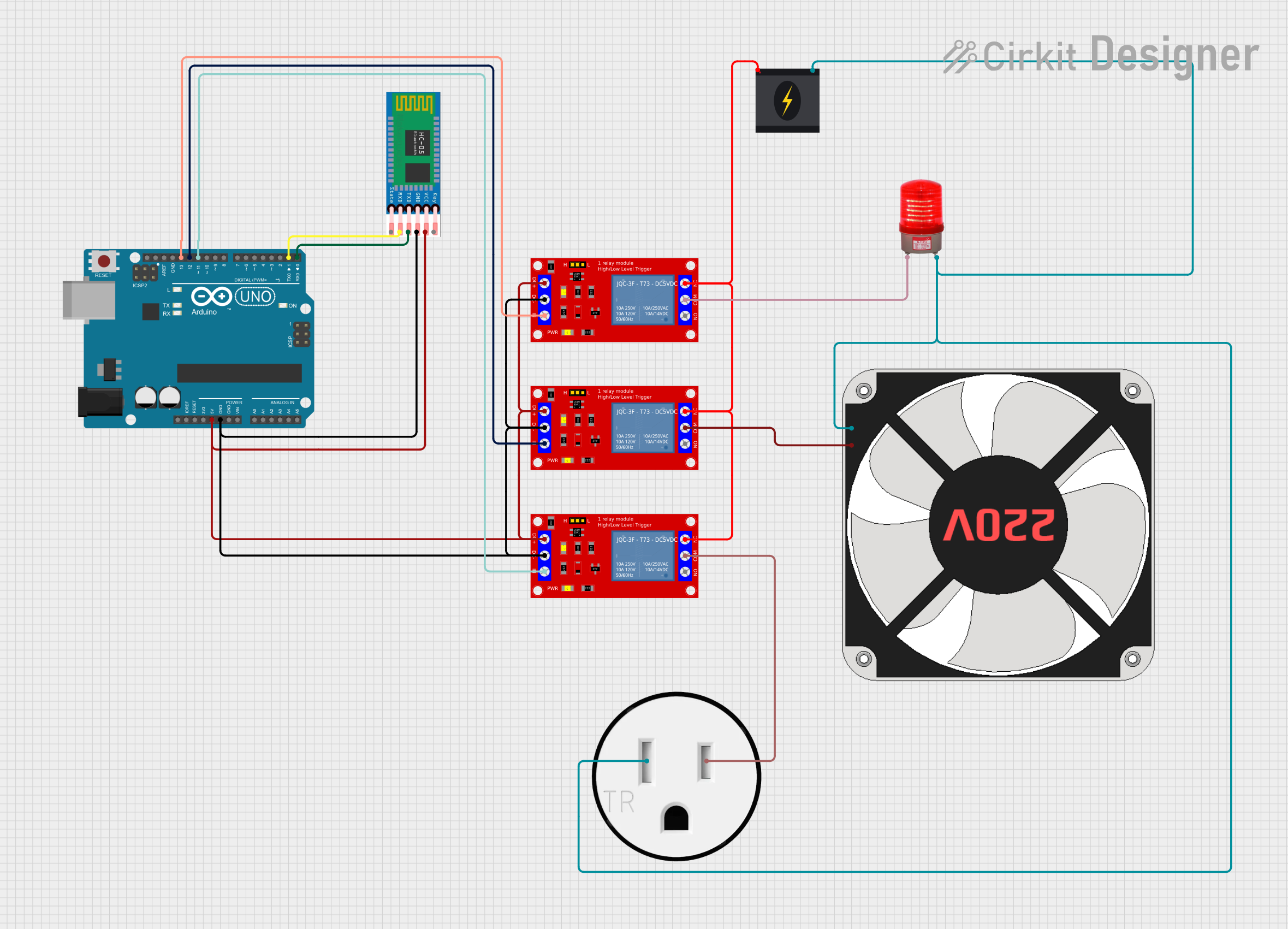
The circuit in question is designed to interface an Arduino UNO microcontroller with an HC-05 Bluetooth module and control three 5V relay modules. The relays are used to switch various loads, including a 220V fan, a 220V red light, and a 120V outlet. The power for the circuit is provided by a 240V power source, which is also used to supply the high-voltage side of the relays for controlling the connected loads.
Component List
Arduino UNO
- Microcontroller board based on the ATmega328P
- It has 14 digital input/output pins, 6 analog inputs, a 16 MHz quartz crystal, a USB connection, a power jack, an ICSP header, and a reset button.
HC-05
- Bluetooth module for wireless communication
- It has 6 pins for enabling, power supply, ground, and serial communication.
1 Channel 5V Relay Module (x3)
- Electromechanical switch with an activation coil driven by 5V
- It has pins for power supply, ground, input signal, and switching contacts (normally open, common, and normally closed).
240V Power Source
- Provides the main power for the circuit and the loads controlled by the relays
- It has two pins for live and neutral wires.
Red Light 220VAC
- An indicator light that operates at 220V AC
- It has two pins for the AC connection.
120V Outlet
- A standard electrical outlet for 120V AC devices
- It has two pins for the AC neutral and hot connections.
220V Fan
- A fan that operates at 220V AC
- It has two pins for the AC live and neutral connections.
Wiring Details
Arduino UNO
5Vpin is connected to the VCC of the HC-05 and the VCC+ of all relay modules.GNDpin is connected to the GND of the HC-05 and the VCC- (GND) of all relay modules.D13pin is connected to the IN pin of one relay module.D12pin is connected to the IN pin of another relay module.D11pin is connected to the IN pin of the third relay module.D1pin (TX) is connected to the RXD pin of the HC-05.D0pin (RX) is connected to the TXD pin of the HC-05.
HC-05
VCCpin is connected to the 5V output from the Arduino UNO.GNDpin is connected to the ground on the Arduino UNO.TXDpin is connected to the D0 (RX) on the Arduino UNO.RXDpin is connected to the D1 (TX) on the Arduino UNO.
1 Channel 5V Relay Module
VCC+pin is connected to the 5V output from the Arduino UNO.VCC- (GND)pin is connected to the ground on the Arduino UNO.INpin is connected to a digital output (D13, D12, or D11) on the Arduino UNO.COMpin is connected to the live wire of the load it controls (fan, outlet, or light).N.C.pin is connected to the live wire from the 240V power source.
240V Power Source
Livepin is connected to the N.C. pins of all relay modules.Neutralpin is connected to the neutral wire of the fan, outlet, and light.
Red Light 220VAC
+pin is connected to the COM pin of one relay module.-pin is connected to the neutral wire from the 240V power source.
120V Outlet
AC Hotpin is connected to the COM pin of one relay module.AC Neutralpin is connected to the neutral wire from the 240V power source.
220V Fan
Lpin is connected to the COM pin of one relay module.Npin is connected to the neutral wire from the 240V power source.
Documented Code
Arduino UNO Code (sketch.ino)
void setup() {
  // put your setup code here, to run once:

}

void loop() {
  // put your main code here, to run repeatedly:

}
The provided code is a template and does not contain any functional code for controlling the relays or interfacing with the HC-05 Bluetooth module. The user is expected to add the necessary code to initialize the serial communication with the HC-05 and to control the relay modules based on the commands received from the Bluetooth module.