Cirkit Designer
Your all-in-one circuit design IDE
Home /
Project Documentation
Arduino Uno-Based Smart Environmental Monitoring System with LCD Display and Sound Detection
Circuit Documentation
Summary
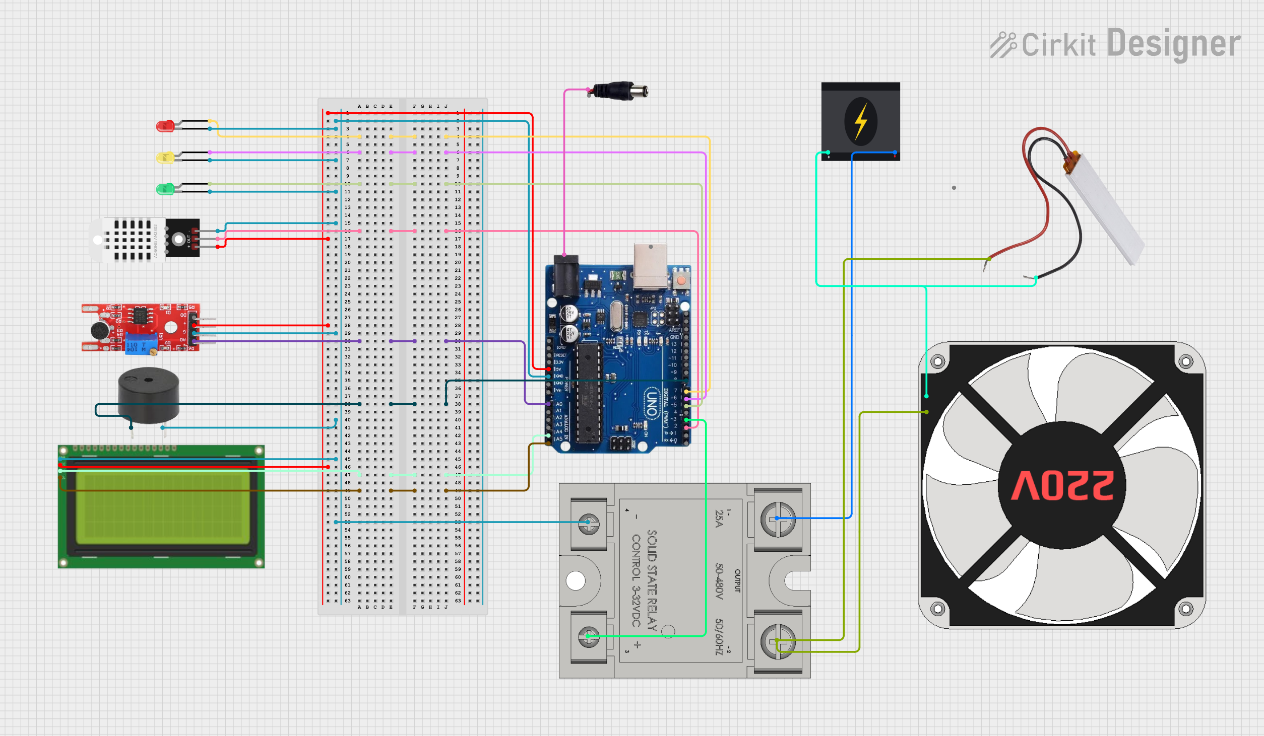
This circuit is designed to monitor environmental conditions using various sensors and display the data on an LCD. It includes temperature and humidity sensing, sound detection, and heartbeat monitoring. The circuit also features visual and auditory alerts using LEDs and a buzzer, and it controls a relay to manage a fan based on temperature thresholds.
Component List
Arduino Uno R3
- Description: Microcontroller board based on the ATmega328P.
- Pins: USB Port, Power Jack, Not Connected, IOREF, RESET, 3.3V, 5V, GND, VIN, A0, A1, A2, A3, A4/SDA, A5/SCL, SCL, SDA, AREF, 13, 12, 11, 10, 9, 8, 7, 6, 5, 4, 3, 2, 1, 0
LED: Two Pin (red)
- Description: Red LED for visual indication.
- Pins: cathode, anode
DHT22
- Description: Temperature and humidity sensor.
- Pins: +, Out, -
KY 038
- Description: Sound sensor module.
- Pins: +, G, A0, D0
LED: Two Pin (yellow)
- Description: Yellow LED for visual indication.
- Pins: cathode, anode
LED: Two Pin (green)
- Description: Green LED for visual indication.
- Pins: cathode, anode
Lcd 20x4 i2c
- Description: 20x4 character LCD with I2C interface.
- Pins: GND, 5v, SCA, SCL
220 fan
- Description: 220V fan for cooling.
- Pins: N, L
240v Power Source
- Description: 240V AC power source.
- Pins: Live, Neutral
PTC
- Description: Positive Temperature Coefficient thermistor.
- Pins: Neutral, Live
SSR-25A
- Description: Solid State Relay for switching high voltage.
- Pins: -, +, 1-in, 2-out
buzzer
- Description: Buzzer for auditory alerts.
- Pins: PIN, GND
power jack
- Description: Power jack for connecting external power.
- Pins: POSITIF, NEGATIF
Wiring Details
Arduino Uno R3
- Power Jack: Connected to
POSITIFof the power jack. - 5V: Connected to
+of DHT22,+of KY 038, and5vof Lcd 20x4 i2c. - GND: Connected to
cathodeof red LED,GNDof buzzer,-of SSR-25A,-of DHT22,Gof KY 038,cathodeof yellow LED,cathodeof green LED, andGNDof Lcd 20x4 i2c. - A0: Connected to
A0of KY 038. - A4/SDA: Connected to
SCAof Lcd 20x4 i2c. - A5/SCL: Connected to
SCLof Lcd 20x4 i2c. - 8: Connected to
PINof buzzer. - 7: Connected to
anodeof red LED. - 6: Connected to
anodeof yellow LED. - 5: Connected to
anodeof green LED. - 3: Connected to
+of SSR-25A. - 2: Connected to
Outof DHT22.
LED: Two Pin (red)
- cathode: Connected to
GNDof Arduino Uno R3. - anode: Connected to
7of Arduino Uno R3.
DHT22
- +: Connected to
5Vof Arduino Uno R3. - Out: Connected to
2of Arduino Uno R3. - -: Connected to
GNDof Arduino Uno R3.
KY 038
- +: Connected to
5Vof Arduino Uno R3. - G: Connected to
GNDof Arduino Uno R3. - A0: Connected to
A0of Arduino Uno R3.
LED: Two Pin (yellow)
- cathode: Connected to
GNDof Arduino Uno R3. - anode: Connected to
6of Arduino Uno R3.
LED: Two Pin (green)
- cathode: Connected to
GNDof Arduino Uno R3. - anode: Connected to
5of Arduino Uno R3.
Lcd 20x4 i2c
- GND: Connected to
GNDof Arduino Uno R3. - 5v: Connected to
5Vof Arduino Uno R3. - SCA: Connected to
A4/SDAof Arduino Uno R3. - SCL: Connected to
A5/SCLof Arduino Uno R3.
220 fan
- N: Connected to
Neutralof PTC. - L: Connected to
Liveof PTC.
240v Power Source
- Live: Connected to
1-inof SSR-25A. - Neutral: Connected to
Neutralof PTC.
PTC
- Neutral: Connected to
Neutralof 240v Power Source andNof 220 fan. - Live: Connected to
Lof 220 fan and2-outof SSR-25A.
SSR-25A
- -: Connected to
GNDof Arduino Uno R3. - +: Connected to
3of Arduino Uno R3. - 1-in: Connected to
Liveof 240v Power Source. - 2-out: Connected to
Liveof PTC.
buzzer
- PIN: Connected to
8of Arduino Uno R3. - GND: Connected to
GNDof Arduino Uno R3.
power jack
- POSITIF: Connected to
Power Jackof Arduino Uno R3.
Code Documentation
#include <DHT.h>
#include <LiquidCrystal_I2C.h>

// DHT22 configuration
#define DHTPIN 2         // Pin connected to the DHT22 data pin
#define DHTTYPE DHT22
DHT dht(DHTPIN, DHTTYPE);

// LED pins
#define GREEN_LED 4
#define YELLOW_LED 5
#define RED_LED 6

// Sound sensor pins
#define SOUND_SENSOR_PIN 3  // Digital out pin
#define SOUND_SENSOR_ANALOG_PIN A1  // Analog out pin

// Heartbeat sensor pin
#define HEARTBEAT_PIN A0

// Buzzer pin
#define BUZZER_PIN 7

// Relay pin
#define RELAY_PIN 8

// LCD configuration
LiquidCrystal_I2C lcd(0x27, 20, 4);  // Adjust the I2C address if necessary

void setup() {
  // Initialize serial communication
  Serial.begin(9600);

  // Initialize the DHT sensor
  dht.begin();

  // Initialize LCD
  lcd.begin(20, 4); // Use 20 columns and 4 rows
  lcd.backlight();

  // Initialize pins
  pinMode(GREEN_LED, OUTPUT);
  pinMode(YELLOW_LED, OUTPUT);
  pinMode(RED_LED, OUTPUT);
  pinMode(SOUND_SENSOR_PIN, INPUT);
  pinMode(HEARTBEAT_PIN, INPUT);
  pinMode(BUZZER_PIN, OUTPUT);
  pinMode(RELAY_PIN, OUTPUT);

  // Turn on relay initially
  digitalWrite(RELAY_PIN, HIGH);
}

void loop() {
  // Read temperature and humidity
  float temperature = dht.readTemperature();
  float humidity = dht.readHumidity();

  // Read heartbeat sensor value
  int heartbeatValue = analogRead(HEARTBEAT_PIN);
  float heartbeatRate = map(heartbeatValue, 0, 1023, 60, 160); // Adjust mapping as needed

  // Read sound sensor value
  int soundDetected = digitalRead(SOUND_SENSOR_PIN);
  int soundLevel = analogRead(SOUND_SENSOR_ANALOG_PIN); // Read analog sound level

  // Display temperature, humidity, and heartbeat on LCD
  lcd.setCursor(0, 0);
  lcd.print("Temp: ");
  lcd.print(temperature);
  lcd.print("C ");
  lcd.print("Hum: ");
  lcd.print(humidity);
  lcd.print("%");

  lcd.setCursor(0, 1);
  lcd.print("Heart: ");
  lcd.print(heartbeatRate);
  lcd.print(" bpm