
ESP8266-Based Smart Environmental Monitoring System with OLED Display
View and Edit Project In Cirkit Designer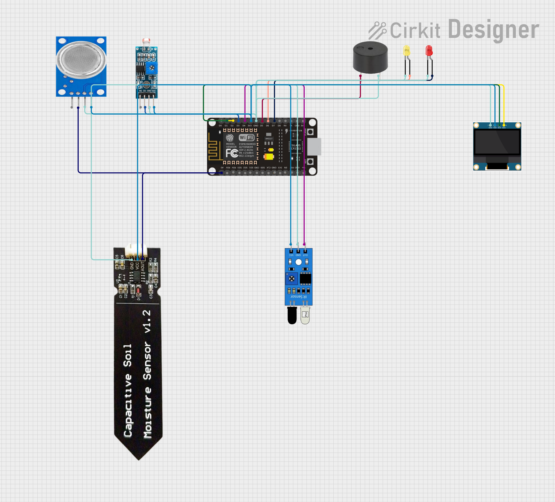
Circuit Documentation
Summary
This document provides a detailed overview of a circuit that integrates an ESP8266 NodeMCU microcontroller with various sensors and output devices. The circuit includes an OLED display, LEDs, a buzzer, an LDR module, a capacitive soil moisture sensor, an MQ135 gas sensor, and an IR sensor. The ESP8266 NodeMCU serves as the central controller, interfacing with all other components to perform various sensing and output functions.
Component List
ESP8266 NodeMCU
- Description: A low-cost Wi-Fi microcontroller with GPIO, ADC, and other interfaces.
- Pins: D0, D1, D2, D3, D4, 3V3, GND, D5, D6, D7, D8, RX, TX, A0, RSV, SD3, SD2, SD1, CMD, SD0, CLK, EN, RST, VIN
LED: Two Pin (Yellow)
- Description: A yellow LED with two pins.
- Pins: Cathode, Anode
LED: Two Pin (Red)
- Description: A red LED with two pins.
- Pins: Cathode, Anode
0.96" OLED
- Description: A small OLED display for visual output.
- Pins: GND, VDD, SCK, SDA
Module LDR
- Description: A light-dependent resistor module for light sensing.
- Pins: VCC, GND, DO, AO
Buzzer
- Description: A simple buzzer for audio output.
- Pins: PIN, GND
Capacitive Soil Moisture Sensor V1.2
- Description: A sensor for measuring soil moisture levels.
- Pins: GND, VCC, AOUT
MQ135
- Description: A gas sensor for detecting air quality.
- Pins: VCC, GND, A0, D0
IR Sensor
- Description: An infrared sensor for object detection.
- Pins: Out, GND, VCC
Wiring Details
ESP8266 NodeMCU
- D1: Connected to SCK of the 0.96" OLED
- D2: Connected to SDA of the 0.96" OLED
- D3: Connected to DO of the Module LDR
- D4: Connected to Out of the IR Sensor
- 3V3: Connected to VCC of the Module LDR, Capacitive Soil Moisture Sensor V1.2, 0.96" OLED, MQ135, and IR Sensor
- GND: Connected to GND of the Module LDR, LED (Red), Capacitive Soil Moisture Sensor V1.2, LED (Yellow), 0.96" OLED, Buzzer, MQ135, and IR Sensor
- D5: Connected to PIN of the Buzzer
- D6: Connected to Anode of the LED (Yellow)
- D7: Connected to Anode of the LED (Red)
- A0: Connected to AOUT of the Capacitive Soil Moisture Sensor V1.2 and A0 of the MQ135
LED: Two Pin (Yellow)
- Cathode: Connected to GND
- Anode: Connected to D6 of the ESP8266 NodeMCU
LED: Two Pin (Red)
- Cathode: Connected to GND
- Anode: Connected to D7 of the ESP8266 NodeMCU
0.96" OLED
- GND: Connected to GND
- VDD: Connected to 3V3
- SCK: Connected to D1 of the ESP8266 NodeMCU
- SDA: Connected to D2 of the ESP8266 NodeMCU
Module LDR
- VCC: Connected to 3V3
- GND: Connected to GND
- DO: Connected to D3 of the ESP8266 NodeMCU
- AO: Not connected
Buzzer
- PIN: Connected to D5 of the ESP8266 NodeMCU
- GND: Connected to GND
Capacitive Soil Moisture Sensor V1.2
- GND: Connected to GND
- VCC: Connected to 3V3
- AOUT: Connected to A0 of the ESP8266 NodeMCU
MQ135
- VCC: Connected to 3V3
- GND: Connected to GND
- A0: Connected to A0 of the ESP8266 NodeMCU
- D0: Not connected
IR Sensor
- Out: Connected to D4 of the ESP8266 NodeMCU
- GND: Connected to GND
- VCC: Connected to 3V3
Code
No code is provided for this circuit.