
Arduino-Controlled Dual Servo Motion System with MPU-6050 and Battery Management
View and Edit Project In Cirkit Designer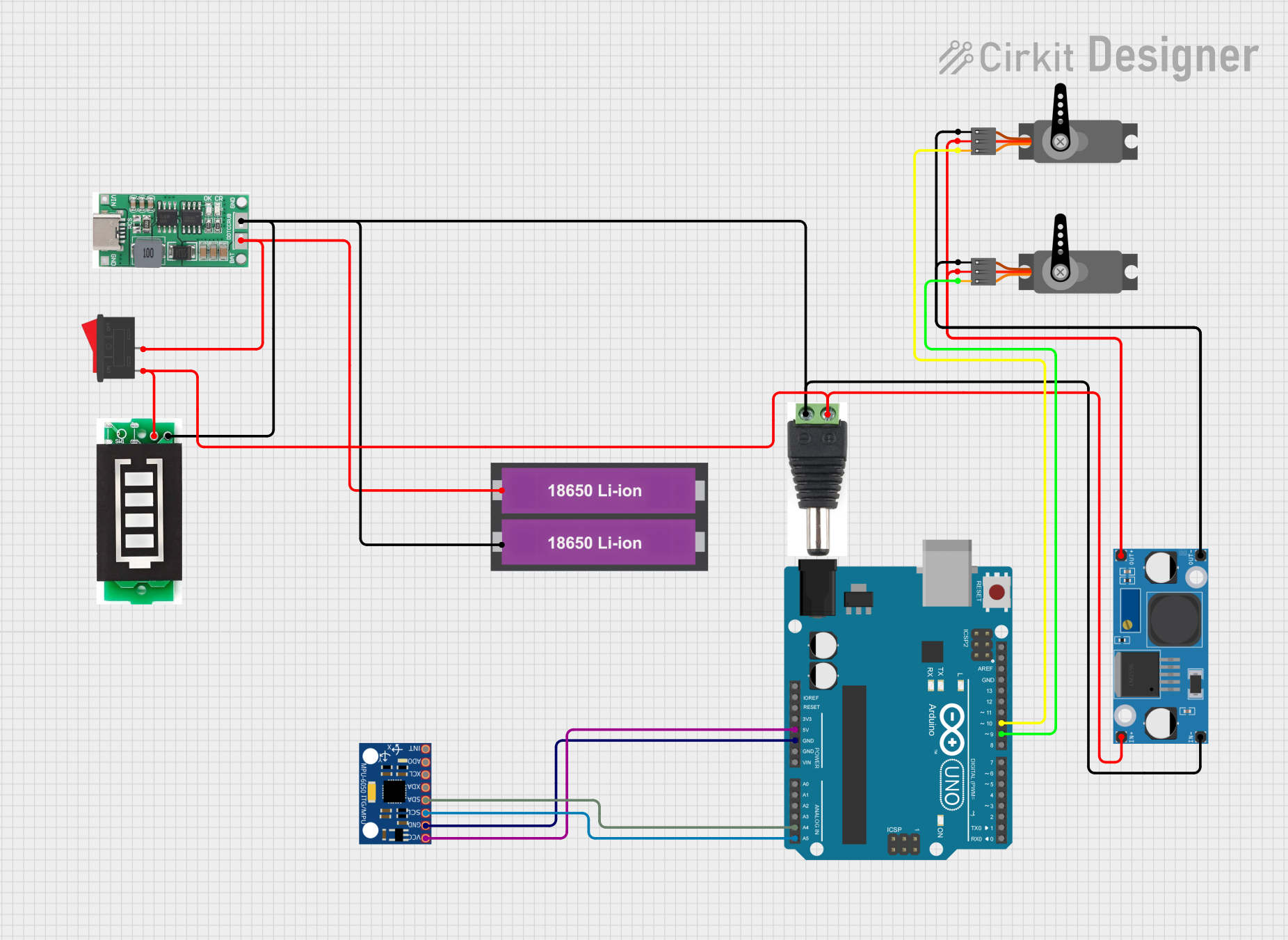
Circuit Documentation
Summary of the Circuit
This circuit is designed to utilize a dual 18650 Li-ion battery configuration to power various components including an MPU-6050 sensor, an Arduino UNO microcontroller, two servos, a battery indicator, and a charging module. The power from the batteries is managed by a rocker switch and regulated by an LM2956 buck converter. The Arduino UNO is used to control the servos and communicate with the MPU-6050 sensor via I2C. The battery indicator provides visual feedback on the battery status, and the charging module facilitates battery charging.
Component List
18650 Li-ion Battery x 2
- Description: A pair of 18650 lithium-ion rechargeable batteries.
- Pins:
+,-
MPU-6050
- Description: A motion processing unit that contains a 3-axis gyroscope and a 3-axis accelerometer.
- Pins:
VCC,GND,SCL,SDA,XDA,XCL,AD0,INT
Arduino UNO
- Description: A microcontroller board based on the ATmega328P.
- Pins:
UNUSED,IOREF,Reset,3.3V,5V,GND,Vin,A0toA5,SCL,SDA,AREF,D13toD0
LM2956 Buck Converter DC-DC
- Description: A DC-DC step-down (buck) converter module.
- Pins:
OUT+,OUT-,IN+,IN-
Battery Indicator
- Description: A module that indicates the charge level of the battery.
- Pins:
+,-
2S Charging Module
- Description: A charging module designed for 2S lithium-ion battery configurations.
- Pins:
BAT +,GND
Rocker Switch
- Description: A simple on-off switch to control the power flow in the circuit.
- Pins:
1,2
Servo
- Description: An actuator capable of precise angular positioning.
- Pins:
GND,VCC,PWM
2.1mm Male
- Description: A male power connector commonly used for DC power supply.
- Pins:
+,-
Wiring Details
18650 Li-ion Battery x 2
+connected to Rocker Switch pin2and 2S Charging Module pinBAT +-connected to Battery Indicator pin-, 2S Charging Module pinGND, 2.1mm Male pin-, and LM2956 Buck Converter pinIN-
MPU-6050
VCCconnected to Arduino UNO pin5VGNDconnected to Arduino UNO pinGNDSCLconnected to Arduino UNO pinA5SDAconnected to Arduino UNO pinA4
Arduino UNO
5VandGNDconnected to MPU-6050 pinsVCCandGNDrespectivelyA5(SCL) andA4(SDA) connected to MPU-6050 pinsSCLandSDArespectivelyD10connected to Servo (instance 1) pinPWMD9connected to Servo (instance 2) pinPWM
LM2956 Buck Converter DC-DC
OUT+connected to both Servos'VCCpinsOUT-connected to both Servos'GNDpinsIN+connected to Rocker Switch pin1, Battery Indicator pin+, 2.1mm Male pin+IN-connected to 18650 Li-ion Battery x 2 pin-
Battery Indicator
+connected to Rocker Switch pin1and LM2956 Buck Converter pinIN+-connected to 18650 Li-ion Battery x 2 pin-
2S Charging Module
BAT +connected to 18650 Li-ion Battery x 2 pin+GNDconnected to 18650 Li-ion Battery x 2 pin-
Rocker Switch
- Pin
1connected to Battery Indicator pin+, 2.1mm Male pin+, and LM2956 Buck Converter pinIN+ - Pin
2connected to 18650 Li-ion Battery x 2 pin+
Servo (instance 1)
PWMconnected to Arduino UNO pinD10VCCandGNDconnected to LM2956 Buck Converter pinsOUT+andOUT-respectively
Servo (instance 2)
PWMconnected to Arduino UNO pinD9VCCandGNDconnected to LM2956 Buck Converter pinsOUT+andOUT-respectively
2.1mm Male
+connected to Rocker Switch pin1and LM2956 Buck Converter pinIN+-connected to 18650 Li-ion Battery x 2 pin-
Documented Code
Arduino UNO Code (sketch.ino)
void setup() {
  // put your setup code here, to run once:

}

void loop() {
  // put your main code here, to run repeatedly:

}
Note: The provided code is a template and does not contain any functional code specific to the circuit's operation. It will need to be populated with the necessary setup and loop code to control the MPU-6050 sensor and the servos.