
Circuit Documentation
Summary
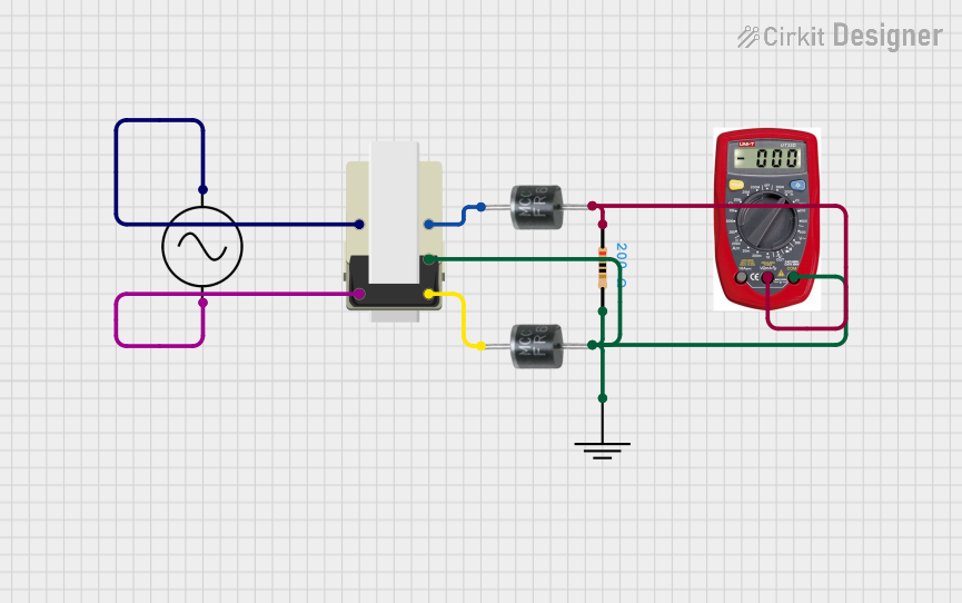
This document provides a detailed overview of a circuit consisting of a transformer, an AC supply, diodes, a resistor, a ground connection, and a multimeter. The circuit is designed to demonstrate the transformation of AC voltage and its rectification using diodes, with measurements taken using a multimeter.
Component List
Transformer
- Description: A device that transfers electrical energy between two or more circuits through electromagnetic induction.
- Pins: 5, 1, 2, 3, 4
AC Supply
- Description: Provides alternating current (AC) power to the circuit.
- Pins: +ve, -ve
FR607 Diode (x2)
- Description: A fast recovery diode used for rectification.
- Pins: Cathode, Anode
Resistor
- Description: A passive electrical component that provides resistance to the flow of current.
- Pins: pin1, pin2
- Properties:
- Resistance: 200 Ohms
GND
- Description: Ground connection for the circuit.
- Pins: GND
Multimeter
- Description: An instrument used to measure voltage, current, and resistance.
- Pins: COM, V, A
Wiring Details
Transformer
- Pin 5 is connected to the Cathode of the first FR607 diode.
- Pin 1 is connected to the +ve pin of the AC Supply.
- Pin 2 is connected to the -ve pin of the AC Supply.
- Pin 3 is connected to the Cathode of the second FR607 diode.
- Pin 4 is connected to:
- pin2 of the Resistor
- GND pin of the GND component
- Anode of the second FR607 diode
- COM pin of the Multimeter
AC Supply
- +ve pin is connected to Pin 1 of the Transformer.
- -ve pin is connected to Pin 2 of the Transformer.
FR607 Diode (First)
- Cathode is connected to Pin 5 of the Transformer.
- Anode is connected to:
- pin1 of the Resistor
- V pin of the Multimeter
FR607 Diode (Second)
- Cathode is connected to Pin 3 of the Transformer.
- Anode is connected to:
- Pin 4 of the Transformer
- COM pin of the Multimeter
Resistor
- pin1 is connected to:
- Anode of the first FR607 diode
- V pin of the Multimeter
- pin2 is connected to:
- Pin 4 of the Transformer
- GND pin of the GND component
- Anode of the second FR607 diode
- COM pin of the Multimeter
GND
- GND pin is connected to:
- Pin 4 of the Transformer
- pin2 of the Resistor
- Anode of the second FR607 diode
- COM pin of the Multimeter
Multimeter
- COM pin is connected to:
- Pin 4 of the Transformer
- pin2 of the Resistor
- Anode of the second FR607 diode
- V pin is connected to:
- pin1 of the Resistor
- Anode of the first FR607 diode
Code
There is no microcontroller code associated with this circuit.
This document provides a comprehensive overview of the circuit, including a summary, detailed component list, wiring details, and code documentation.