
ESP32E-Powered Audio Recorder with SoftPot Interface and Playback
View and Edit Project In Cirkit Designer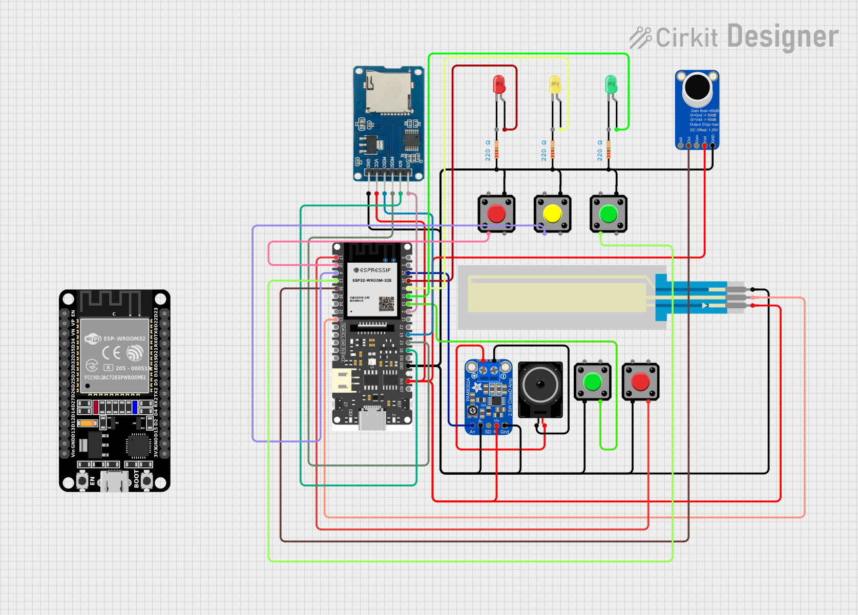
Circuit Documentation
Summary
This circuit integrates various components including microcontrollers, sensors, audio modules, and user interface elements. The primary microcontrollers are the ESP32 and ESP32E, which are responsible for controlling the circuit's behavior and interfacing with the other components. The SoftPot Membrane Potentiometer is used as a sensor input, while the Adafruit PAM8302 amplifier and Adafruit MAX9814 microphone amplifier are used for audio input and output. The circuit also includes a Micro SD Card Module for data storage, multiple pushbuttons for user input, and LEDs for visual feedback. The circuit is powered through the 3V3 and GND connections of the ESP32E.
Component List
Microcontrollers
- ESP32 (30 pin): A powerful microcontroller with Wi-Fi and Bluetooth capabilities.
- ESP32E: A variant of the ESP32 with similar features and a different pin layout.
Sensors
- SoftPot Membrane Potentiometer - 50mm: A thin and flexible potentiometer that changes resistance as pressure is applied to its surface.
Audio Components
- Adafruit PAM8302: A 2.5W Class D single-channel audio amplifier.
- Adafruit MAX9814 Electret Microphone Amplifier: An automatic gain control microphone amplifier for capturing audio signals.
- Loudspeaker: An audio output device to play sounds.
User Interface
- Pushbuttons: Simple switches that connect two points in a circuit when pressed.
- LED: Two Pin (red, green, yellow): Light-emitting diodes that emit red, green, or yellow light when powered.
Storage
- Micro SD Card Module: A module that allows an SD card to be read from and written to by a microcontroller.
Passive Components
- Resistor: A component that resists the flow of current, used here with a resistance of 220 Ohms to limit current to LEDs and other components.
Wiring Details
SoftPot Membrane Potentiometer - 50mm
- wiper connected to ESP32E pin 15
- leg2 connected to ESP32E GND
- leg1 connected to ESP32E 3V3
Adafruit PAM8302
- GND connected to ESP32E GND, Pushbuttons, Adafruit MAX9814 Electret Microphone Amplifier GND, and Micro SD Card Module gnd
- VCC connected to ESP32E 3V3
- SD not connected
- AIN- connected to ESP32E GND
- AIN+ connected to ESP32E pin 25
- VO- connected to Loudspeaker pin1
- VO+ connected to Loudspeaker pin2
Adafruit MAX9814 Electret Microphone Amplifier
- GND connected to ESP32E GND
- VDD connected to ESP32E 3V3
- GAIN not connected
- OUTPUT connected to ESP32E pin 36
- A/R not connected
LEDs (Red, Green, Yellow)
- cathode (for all LEDs) connected to ESP32E GND
- anode (Red) connected to ESP32E pin 26
- anode (Green) connected to ESP32E pin 14
- anode (Yellow) connected to ESP32E pin 0
Pushbuttons
- Pin 2 (for all pushbuttons) connected to ESP32E pins 13, 17, 16, 4, 12, and GND through resistors
- Pin 1 not connected
- Pin 3 (for all pushbuttons) connected to ESP32E pins 13, 17, 16, 4, 12
- Pin 4 (for all pushbuttons) connected to ESP32E GND
Resistor
- pin1 (for all resistors) connected to Pushbuttons Pin 2 and ESP32E GND
- pin2 (for all resistors) connected to ESP32E GND
Micro SD Card Module
- cs connected to ESP32E pin 2
- sck connected to ESP32E pin 18
- mosi connected to ESP32E pin 23
- miso connected to ESP32E pin 19
- vcc connected to ESP32E 3V3
- gnd connected to ESP32E GND
Loudspeaker
- pin1 connected to Adafruit PAM8302 VO-
- pin2 connected to Adafruit PAM8302 VO+
Documented Code
There is no code provided for the microcontrollers in this circuit. The functionality of the circuit will depend on the embedded code that is written and uploaded to the ESP32 and ESP32E microcontrollers. The code would typically initialize the hardware components, handle the logic for sensor readings, user inputs, audio processing, and manage communication with the Micro SD Card Module. Without the code, the specific behavior of the circuit cannot be documented.