Cirkit Designer
Your all-in-one circuit design IDE
Home /
Project Documentation
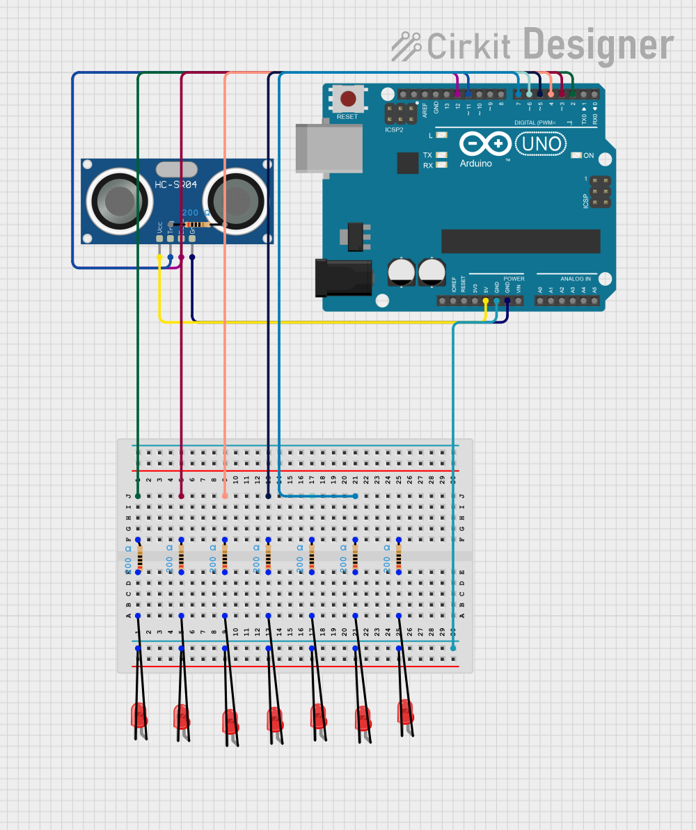
Arduino UNO Ultrasonic Distance Sensor with LED Indicators
Circuit Documentation
Summary
This circuit consists of an Arduino UNO microcontroller, an HC-SR04 Ultrasonic Sensor, multiple red LEDs, and resistors. The Arduino UNO is used to control the LEDs and read distance measurements from the ultrasonic sensor. The LEDs are connected through resistors to the digital pins of the Arduino, and the ultrasonic sensor is connected to the Arduino to measure distances.
Component List
Arduino UNO
- Description: A microcontroller board based on the ATmega328P.
- Pins: UNUSED, IOREF, Reset, 3.3V, 5V, GND, Vin, A0, A1, A2, A3, A4, A5, SCL, SDA, AREF, D13, D12, D11, D10, D9, D8, D7, D6, D5, D4, D3, D2, D1, D0
HC-SR04 Ultrasonic Sensor
- Description: A sensor used to measure distance by using ultrasonic waves.
- Pins: VCC, TRIG, ECHO, GND
LED: Two Pin (red)
- Description: A red light-emitting diode.
- Pins: cathode, anode
Resistor
- Description: A passive electrical component that limits current flow.
- Pins: pin1, pin2
- Properties: Resistance = 200 Ohms
Wiring Details
Arduino UNO
- D2: Connected to pin2 of a Resistor
- D3: Connected to pin2 of a Resistor
- D4: Connected to pin2 of a Resistor
- D5: Connected to pin2 of a Resistor
- D6: Connected to pin2 of a Resistor
- D7: Connected to pin2 of a Resistor
- GND: Connected to the cathode of multiple LEDs
- 5V: Connected to VCC of the HC-SR04 Ultrasonic Sensor
- GND: Connected to GND of the HC-SR04 Ultrasonic Sensor
- D12: Connected to ECHO of the HC-SR04 Ultrasonic Sensor
- D11: Connected to TRIG of the HC-SR04 Ultrasonic Sensor
HC-SR04 Ultrasonic Sensor
- VCC: Connected to 5V of the Arduino UNO
- TRIG: Connected to D11 of the Arduino UNO
- ECHO: Connected to D12 of the Arduino UNO
- GND: Connected to GND of the Arduino UNO
LED: Two Pin (red)
- cathode: Connected to GND of the Arduino UNO
- anode: Connected to pin1 of a Resistor
Resistor
- pin1: Connected to the anode of an LED
- pin2: Connected to a digital pin of the Arduino UNO (D2, D3, D4, D5, D6, D7)
Documented Code
const int echo = 13;
const int trig = 12;

int duration = 0;
int distance = 0;

void setup()
{
  pinMode(trig , OUTPUT);
  pinMode(echo , INPUT);

  Serial.begin(9600);
}

void loop()
{
  digitalWrite(trig , HIGH);
  delayMicroseconds(1000);
  digitalWrite(trig , LOW);

  duration = pulseIn(echo , HIGH);
  distance = (duration/2) / 29.1 ;
  Serial.println(distance);
}
- echo: Pin 13 on the Arduino UNO, used to read the echo signal from the HC-SR04 Ultrasonic Sensor.
- trig: Pin 12 on the Arduino UNO, used to send the trigger signal to the HC-SR04 Ultrasonic Sensor.
- duration: Variable to store the time duration of the echo signal.
- distance: Variable to store the calculated distance based on the echo duration.
Setup Function
- pinMode(trig, OUTPUT): Sets the trig pin as an output.
- pinMode(echo, INPUT): Sets the echo pin as an input.
- Serial.begin(9600): Initializes serial communication at a baud rate of 9600.
Loop Function
- digitalWrite(trig, HIGH): Sends a high signal to the trig pin.
- delayMicroseconds(1000): Waits for 1000 microseconds.
- digitalWrite(trig, LOW): Sends a low signal to the trig pin.
- duration = pulseIn(echo, HIGH): Measures the duration of the high signal on the echo pin.
- distance = (duration/2) / 29.1: Calculates the distance based on the duration.
- Serial.println(distance): Prints the distance to the serial monitor.