
Solar-Powered Arduino-Controlled Robotics Platform with Bluetooth Connectivity and Environmental Sensing
View and Edit Project In Cirkit Designer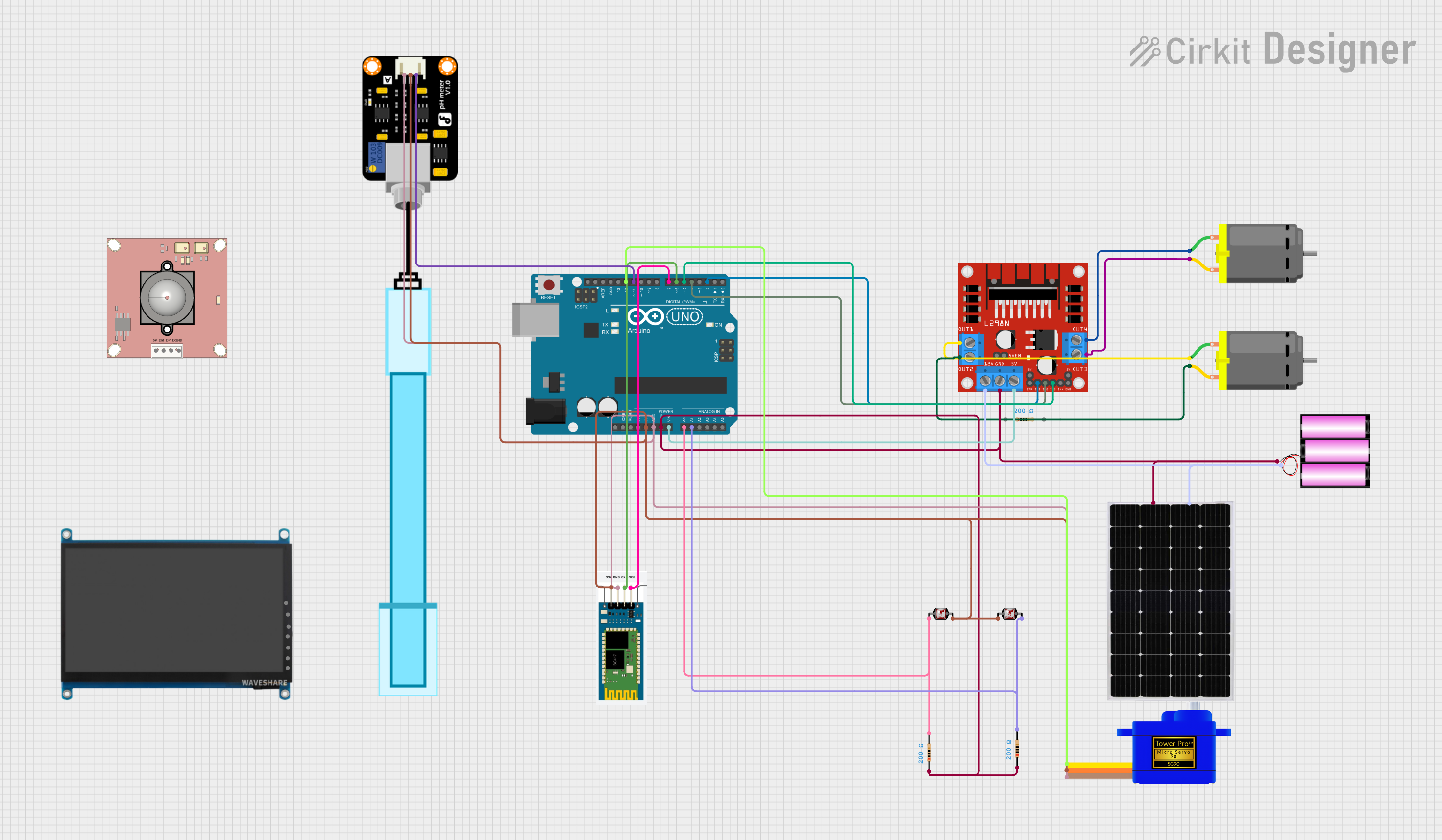
Circuit Documentation
Summary
The circuit in question is designed to control and power various components including DC motors, a camera module, a motor driver, an Arduino UNO microcontroller, sensors, a display, a Bluetooth module, a servo motor, a pH meter, and power sources such as a solar panel and a 12V battery. The Arduino UNO serves as the central processing unit, interfacing with sensors and controlling the motors via the L298N motor driver. The circuit is powered by a combination of a solar panel and a 12V battery, ensuring a stable power supply for all components.
Component List
DC Motor
- Description: An electric motor that runs on direct current (DC) electricity.
- Pins: pin 1, pin 2
IMX179 Camera Module
- Description: A camera module capable of capturing high-resolution images and video.
- Pins: 5V, D-, D+, GND
L298N DC Motor Driver
- Description: A module used to control the direction and speed of DC motors.
- Pins: OUT1, OUT2, 12V, GND, 5V, OUT3, OUT4, 5V-ENA-JMP-I, 5V-ENA-JMP-O, +5V-J1, +5V-J2, ENA, IN1, IN2, IN3, IN4, ENB
Arduino UNO
- Description: A microcontroller board based on the ATmega328P, used for controlling the logic of the circuit.
- Pins: UNUSED, IOREF, Reset, 3.3V, 5V, GND, Vin, A0, A1, A2, A3, A4, A5, SCL, SDA, AREF, D13, D12, D11, D10, D9, D8, D7, D6, D5, D4, D3, D2, D1, D0
Resistor
- Description: A passive two-terminal electrical component that implements electrical resistance as a circuit element.
- Properties: Resistance - 200 Ohms
Photocell (LDR)
- Description: A light-dependent resistor whose resistance decreases with increasing incident light intensity.
- Pins: pin 0, pin 1
7 inch WaveShare (H) Display
- Description: A 7-inch display with HDMI, VGA, and USB interfaces.
- Pins: HDMI, +, -, USB Power, Touch USB, Audio, VGA
Solar Panel
- Description: A panel designed to absorb the sun's rays as a source of energy for generating electricity.
- Pins: +, -
HC-06 Bluetooth Module
- Description: A Bluetooth module used for wireless communication.
- Pins: RXD, TXD, GND, VCC
Servomotor SG90
- Description: A small and lightweight servo motor capable of precise control.
- Pins: SIG, VCC, GND
12V Battery
- Description: A 12-volt battery used as a power source.
- Pins: +, -
PH Meter
- Description: A sensor used to measure the pH level of a solution.
- Pins: Signal, VCC, GND
Wiring Details
DC Motor
- Connected to L298N DC motor driver OUT1 and OUT2 for motor control.
IMX179 Camera Module
- Powered by 5V and connected to GND. Data lines D- and D+ are not detailed in the net list.
L298N DC Motor Driver
- Motor outputs OUT1, OUT2, OUT3, and OUT4 are connected to DC motors.
- Power input 12V is connected to the solar panel and battery 12V lines.
- Ground (GND) is connected to the solar panel, battery, and Arduino UNO GND.
- Logic inputs IN1, IN2, IN3, and IN4 are controlled by Arduino UNO digital pins D2, D4, D5, and D6 respectively.
- 5V output is connected to Arduino UNO Vin for power.
Arduino UNO
- Digital pins D2, D4, D5, D6, D7, D11, and D12 are used for controlling the motor driver, Bluetooth module, and sensors.
- Analog pins A0 and A1 are connected to photocells through resistors.
- 5V and GND pins are used to power various components in the circuit.
Resistor
- Two 200 Ohm resistors are used in series with photocells and connected to Arduino UNO analog pins A0 and A1.
Photocell (LDR)
- Connected in a voltage divider configuration with resistors to Arduino UNO analog pins A0 and A1.
HC-06 Bluetooth Module
- RXD and TXD are connected to Arduino UNO digital pins D7 and D6 for serial communication.
- VCC and GND are connected to Arduino UNO 5V and GND for power.
Servomotor SG90
- Signal (SIG) pin is connected to Arduino UNO digital pin D12 for control.
- VCC and GND are connected to Arduino UNO 5V and GND for power.
PH Meter
- Signal pin is connected to Arduino UNO digital pin D11 for data reading.
- VCC and GND are connected to Arduino UNO 5V and GND for power.
Documented Code
Arduino UNO - sketch.ino
void setup() {
  // put your setup code here, to run once:

}

void loop() {
  // put your main code here, to run repeatedly:

}
Note: The provided code is a template and does not contain any functional code specific to the circuit. Additional code is required to initialize and control the connected components based on the wiring details.