
Circuit Documentation
Summary of the Circuit
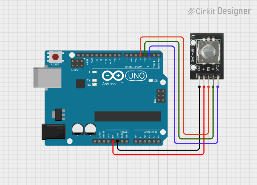
This circuit consists of an Arduino UNO microcontroller board interfaced with an HW-040 Rotary Encoder. The Arduino UNO is responsible for processing the signals generated by the rotary encoder, which typically includes rotational position tracking and a push-button feature. The encoder is powered by the Arduino's 5V output and is grounded to the Arduino's ground (GND). The encoder's SW, DT, and CLK pins are connected to digital pins on the Arduino for signal processing.
Component List
Arduino UNO
- Description: A microcontroller board based on the ATmega328P.
- Pins: UNUSED, IOREF, Reset, 3.3V, 5V, GND, Vin, A0-A5, SCL, SDA, AREF, D0-D13.
- Purpose: Acts as the central processing unit for the circuit, reading the encoder's output and executing embedded code to perform tasks based on the encoder's position and button state.
HW-040 Rotary Encoder
- Description: An incremental rotary encoder with a push-button.
- Pins: GND, +, SW, DT, CLK.
- Purpose: Provides rotational position feedback and a push-button interface to the Arduino.
Wiring Details
Arduino UNO
- 5V to HW-040 Rotary Encoder (+)
- GND to HW-040 Rotary Encoder (GND)
- D4 to HW-040 Rotary Encoder (SW)
- D3 to HW-040 Rotary Encoder (DT)
- D2 to HW-040 Rotary Encoder (CLK)
HW-040 Rotary Encoder
- + to Arduino UNO (5V)
- GND to Arduino UNO (GND)
- SW to Arduino UNO (D4)
- DT to Arduino UNO (D3)
- CLK to Arduino UNO (D2)
Documented Code
sketch.ino
void setup() {
  // put your setup code here, to run once:

}

void loop() {
  // put your main code here, to run repeatedly:

}
documentation.txt
(No additional documentation provided in the code file)
This concludes the documentation for the given circuit. The code provided is a template and does not include specific functionality for interacting with the HW-040 Rotary Encoder. To complete the implementation, code should be added to the setup() function to initialize the encoder's pins as inputs and to the loop() function to read the encoder's state and respond to changes.