
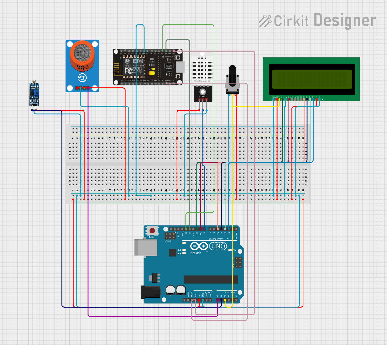
Circuit Documentation
Summary
This circuit is designed to monitor environmental parameters such as light intensity, gas concentration, temperature, and humidity. It utilizes an Arduino UNO as the main microcontroller to process sensor data and control a 16x2 LCD display for output. The circuit includes an LDR module for light sensing, an MQ-3 breakout module for detecting alcohol gas levels, a DHT22 sensor for measuring temperature and humidity, and a rotary potentiometer to adjust the LCD contrast. An ESP8266 NodeMCU is also included, potentially for wireless communication capabilities.
Component List
Arduino UNO
- Microcontroller board based on the ATmega328P
- It has 14 digital input/output pins, 6 analog inputs, a 16 MHz quartz crystal, a USB connection, a power jack, an ICSP header, and a reset button.
LDR Module 3 pin
- A light-dependent resistor module used to detect the level of ambient light.
- It has three pins: VCC, GND, and DO (Digital Output).
MQ-3 Breakout
- A module equipped with an MQ-3 sensor designed to detect alcohol vapor in the air.
- It has four pins: VCC, GND, DO (Digital Output), and AO (Analog Output).
DHT22
- A sensor for measuring temperature and humidity.
- It has three pins: + (VCC), Out (Signal Output), and - (GND).
16X2 LCD
- A liquid crystal display capable of displaying 16 characters per line across 2 lines.
- It has 16 pins including VSS, VDD, V0, RS, RW, E, D0-D7, A (Anode), and K (Cathode).
Rotary Potentiometer
- A variable resistor with a knob used to provide adjustable voltage levels.
- It has three pins: leg1, wiper, and leg2.
- Resistance: 10,000 Ohms
ESP8266 NodeMCU
- A Wi-Fi microchip with integrated TCP/IP protocol stack that can give any microcontroller access to a Wi-Fi network.
- It has multiple GPIOs and specialized pins including D0-D8, RX, TX, A0, RSV, SD3, SD2, SD1, CMD, SD0, CLK, EN, RST, VIN, 3V3, and GND.
Wiring Details
Arduino UNO
- 5V: Powers the LDR module, MQ-3 breakout, DHT22, Rotary Potentiometer, and 16X2 LCD.
- GND: Common ground for LDR module, MQ-3 breakout, ESP8266 NodeMCU, DHT22, Rotary Potentiometer, and 16X2 LCD.
- A1: Connected to the DO pin of the LDR module.
- A0: Connected to the AO pin of the MQ-3 breakout.
- A2: Connected to the wiper of the Rotary Potentiometer.
- D13: Connected to the RX pin of the ESP8266 NodeMCU.
- D12: Connected to the TX pin of the ESP8266 NodeMCU.
- D10: Connected to the RS pin of the 16X2 LCD.
- D9: Connected to the E pin of the 16X2 LCD.
- D8: Connected to the Out pin of the DHT22.
- D5, D4, D3, D2: Connected to the D4, D5, D6, D7 pins of the 16X2 LCD respectively.
LDR Module 3 pin
- VCC: Powered by the Arduino UNO 5V pin.
- GND: Connected to the common ground.
- DO: Connected to the A1 pin of the Arduino UNO.
MQ-3 Breakout
- VCC: Powered by the Arduino UNO 5V pin.
- GND: Connected to the common ground.
- DO: Not connected in this circuit.
- AO: Connected to the A0 pin of the Arduino UNO.
DHT22
-
- (VCC): Powered by the Arduino UNO 5V pin.
- Out: Connected to the D8 pin of the Arduino UNO.
-
- (GND): Connected to the common ground.
16X2 LCD
- VSS: Connected to the common ground.
- VDD: Powered by the Arduino UNO 5V pin.
- V0: Connected to the wiper of the Rotary Potentiometer.
- RS: Connected to the D10 pin of the Arduino UNO.
- RW: Connected to the common ground.
- E: Connected to the D9 pin of the Arduino UNO.
- D4-D7: Connected to the D5-D2 pins of the Arduino UNO respectively.
- A (Anode): Powered by the Arduino UNO 5V pin.
- K (Cathode): Connected to the common ground.
Rotary Potentiometer
- leg1: Connected to the common ground.
- wiper: Connected to the V0 pin of the 16X2 LCD and A2 pin of the Arduino UNO.
- leg2: Powered by the Arduino UNO 5V pin.
ESP8266 NodeMCU
- 3V3: Connected to its own RST pin and the 3.3V pin of the Arduino UNO.
- GND: Connected to the common ground.
- RX: Connected to the D13 pin of the Arduino UNO.
- TX: Connected to the D12 pin of the Arduino UNO.
Documented Code
Arduino UNO Code (sketch.ino)
#include <LiquidCrystal.h>
#include "DHT.h"  // Include DHT sensor library

LiquidCrystal lcd(10, 9, 5, 4, 3, 2);  // Initialize the LCD: RS, E, D4, D5, D6, D7
#define DHTTYPE DHT11
#define LDR_PIN A1
#define MQ3_PIN A0
DHT dht(8, DHTTYPE);  // Initialize DHT sensor on pin 8

// Variables to store sensor readings
float t = 0;  // Temperature
float h = 0;  // Humidity
int ldr_read = 0;  // LDR sensor value
int gas_read = 0;  // MQ3 sensor value

void setup() {
  lcd.begin(16, 2);  // Initialize the LCD with 16 columns and 2 rows
  dht.begin();  // Initialize the DHT sensor

  // Display initial message on the LCD
  lcd.setCursor(0, 0);
  lcd.print(" IoT Based Smart");
  lcd.setCursor(0, 1);
  lcd.print(" Food Monitoring");

  Serial.begin(9600);  // Initialize Serial communication for debugging
  delay(2000);  // Wait for 2 seconds before starting sensor readings
}

void loop() {
  lcd.clear();  // Clear the LCD screen

  // Read LDR and MQ3 sensor values
  ldr_read = 1023 - analogRead(LDR_PIN);  // LDR sensor reading
  gas_read = analogRead(MQ3_PIN);  // MQ3 sensor reading

  // Display LDR and MQ3 sensor values on the LCD
  lcd.setCursor(0, 0);
  lcd.print("LDR-");
  lcd.setCursor(4, 0);
  lcd.print(ldr_read);

  lcd.setCursor(0, 1);
  lcd.print("MQ3-");
  lcd.setCursor(4, 1);
  lcd.print(gas_read);

  // Read temperature and humidity from DHT sensor
  t = dht.readTemperature();  // Temperature in Celsius
  h = dht.readHumidity();  // Humidity percentage

  // Display temperature and humidity on the LCD
  lcd.setCursor(8, 0);
  lcd.print("Tem-");
  lcd.setCursor(12, 0);
  lcd.print(t);

  lcd.setCursor(8, 1);
  lcd.print("Hum-");
  lcd.setCursor(12, 1);
  lcd.print(h);

  // Debugging: Print sensor values to the Serial monitor
  Serial.print("Temperature = ");
  Serial.println(t);
  Serial.print("Humidity = ");
  Serial.println(h);
  Serial.print("LDR = ");
  Serial.println(ldr_read);
  Serial.print("MQ3 = ");
  Serial.println(gas_read);

  delay(2000);  // Wait for 2 seconds before updating the screen again
}
This code is responsible for reading sensor data from the LDR, MQ-3, and DHT22 sensors, displaying the readings on the 16x2 LCD, and outputting the data to the serial monitor for debugging purposes. The LCD is initialized with the appropriate pins, and the DHT sensor is set up with its type and connected pin. The loop function continuously reads sensor values, updates the LCD, and prints the data to the serial monitor.