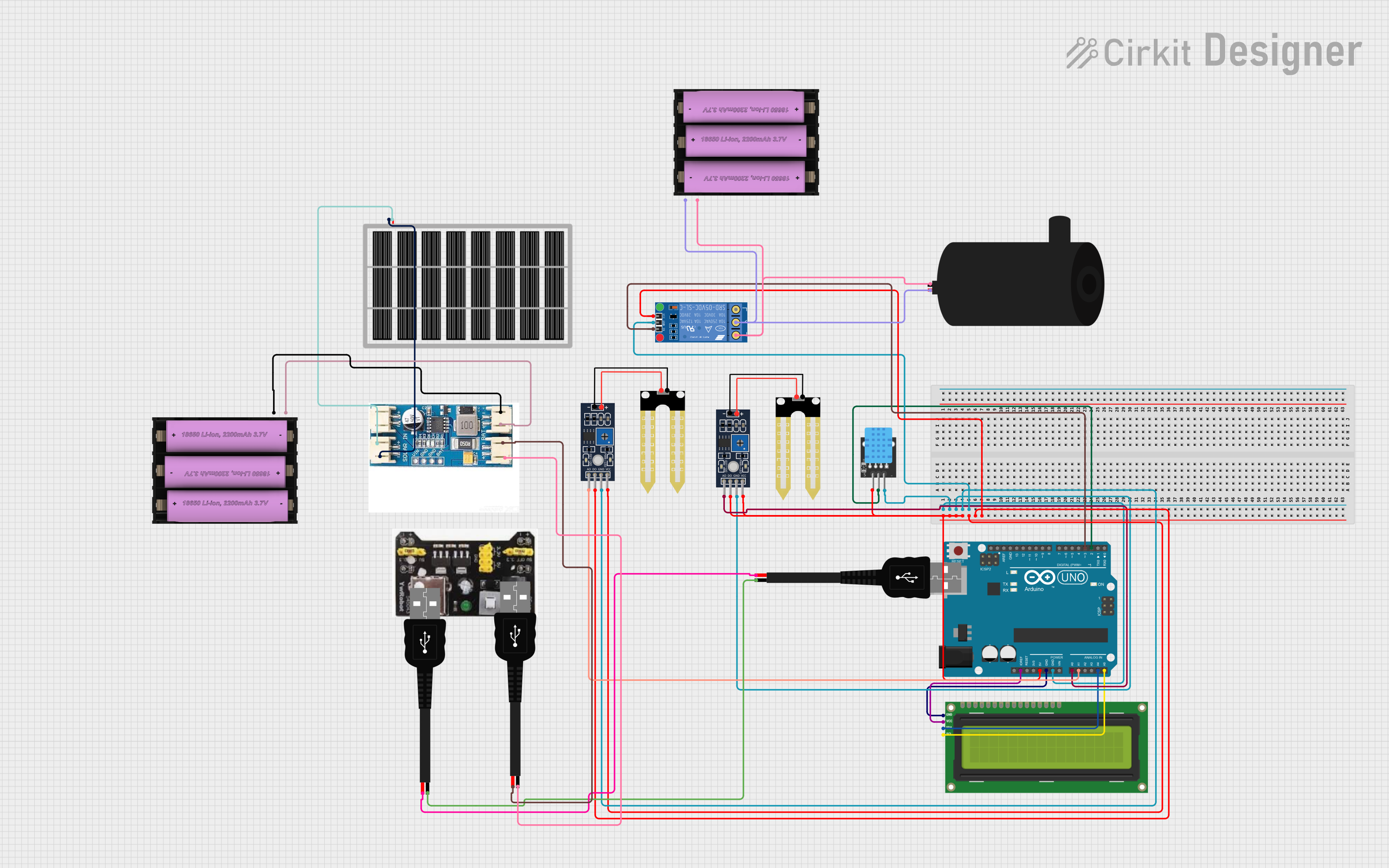
Solar-Powered Arduino Environmental Monitoring and Irrigation System

Circuit Documentation
Summary
This circuit is designed to interface an Arduino UNO with various sensors and modules, including a DHT11 temperature and humidity sensor, two Humidity YL-69 soil moisture sensors, an I2C LCD 16x2 Screen for display, a KF-301 Relay to control a water pump, and a solar power management system consisting of a Solar Panel, a CN3791 MPPT LiPo solar charger, and batteries. The Arduino UNO acts as the central processing unit, reading sensor data and controlling the relay based on predefined conditions.
Component List
Arduino UNO
- Microcontroller board based on the ATmega328P
- Digital I/O pins (14, of which 6 provide PWM output)
- Analog input pins (6)
- A USB connection for programming and serial communication
- ICSP header
- Reset button
I2C LCD 16x2 Screen
- 16 characters wide, 2 rows character LCD
- I2C communication interface
- Backlight and contrast adjustment
DHT11
- Digital temperature and humidity sensor
- Simple digital signal output
Humidity YL-69 (x2)
- Soil moisture sensor
- Analog output (A0)
- Digital output (D0)
Solar Panel
- Photovoltaic panel for converting sunlight into electrical energy
CN3791 MPPT LiPo Solar Charger
- Maximum Power Point Tracking (MPPT) for solar panels
- Charges a single-cell Lithium Polymer (LiPo) battery
Set Battery (7v) (x2)
- 7V battery for power storage
MB102 Breadboard Power Supply Module 3.3V/5V
- Power supply module for breadboards
- Output voltages: 3.3V and 5V
USB Male 2 Pin Connection (x3)
- USB connector with two pins for power connections
KF-301 Relay
- Electromechanical switch with a coil-actuated mechanical relay
- Normally Open (NO), Normally Closed (NC), and Common (C) terminals
Water Pump
- Electric pump for moving water
Wiring Details
Arduino UNO
- 5V and GND pins provide power to the DHT11, both Humidity YL-69 sensors, and the KF-301 Relay.
- A0 and A1 pins are connected to the analog outputs of the two Humidity YL-69 sensors.
- A4 (SDA) and A5 (SCL) pins are connected to the I2C data and clock lines of the I2C LCD 16x2 Screen.
- D2 pin is connected to the signal pin of the DHT11 sensor.
- D3 pin is connected to the signal pin of the KF-301 Relay.
I2C LCD 16x2 Screen
- VCC (5V) and GND pins are connected to the Arduino UNO for power.
- SDA and SCL pins are connected to the corresponding I2C pins on the Arduino UNO.
DHT11
- 5V and GND pins are connected to the Arduino UNO for power.
- S pin is connected to the D2 pin on the Arduino UNO for data signal.
Humidity YL-69
- VCC and GND pins are connected to the Arduino UNO for power.
- A0 pins are connected to the A0 and A1 pins on the Arduino UNO for analog signal.
Solar Panel
- VCC and GND pins are connected to the solar in + and solar in - pins of the CN3791 MPPT LiPo solar charger.
CN3791 MPPT LiPo Solar Charger
- Solar in + and solar in - pins are connected to the Solar Panel.
- Bat in + and bat in - pins are connected to the Set Battery (7v).
- Bat out + and bat out - pins are connected to the USB male 2 pin connection for power output.
Set Battery (7v)
- and - pins are connected to the bat in + and bat in - pins of the CN3791 MPPT LiPo solar charger.
- One battery is also connected to the KF-301 Relay and the water pump for power.
KF-301 Relay
- Power and ground pins are connected to the Arduino UNO for power.
- Signal pin is connected to the D3 pin on the Arduino UNO for control.
- C and NO pins are connected to the water pump and the Set Battery (7v) to control the power to the pump.
Water Pump
- Positive and negative pins are connected to the KF-301 Relay and the Set Battery (7v) for power.
Documented Code
Arduino UNO Code (sketch.ino)
void setup() {
  // put your setup code here, to run once:

}

void loop() {
  // put your main code here, to run repeatedly:

}
This code is a template and does not contain any functional code. It is expected that the user will fill in the setup() and loop() functions with code to initialize the sensors and modules, read sensor data, and control the relay based on the sensor inputs.