Arduino Mega 2560 Controlled Robotics Circuit with Motor Drivers and Actuators
Circuit Documentation
Summary
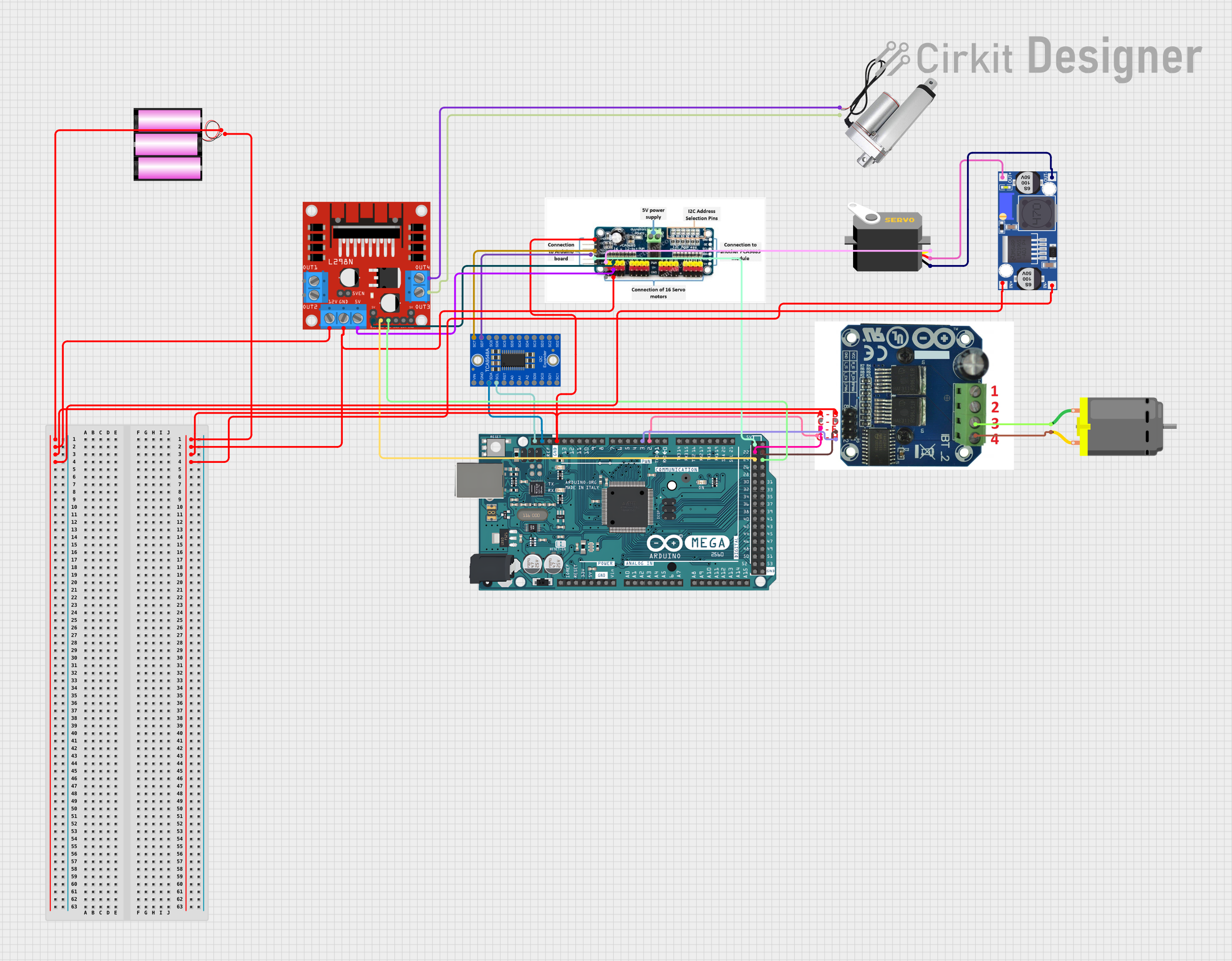
This circuit is designed to control a DC motor and a servo motor using an Arduino Mega 2560 microcontroller. It includes a motor driver (BTS7960) for the DC motor, a PCA9685 module for PWM control, an Adafruit TCA9548A I2C multiplexer for expanding I2C capabilities, and a L298N DC motor driver for controlling a linear actuator. The circuit is powered by a 12V battery, and a buck converter is used to step down the voltage for the servo motor. The Arduino Mega 2560 manages the control signals for the motors and communicates with the I2C devices.
Component List
- Arduino Mega 2560: A microcontroller board based on the ATmega2560 with numerous digital and analog I/O pins.
- DC Motor: A motor that converts electrical energy into mechanical rotation.
- Servo: A rotary actuator that allows for precise control of angular position.
- Linear Actuator: A device that creates motion in a straight line using electrical energy.
- L298N DC Motor Driver: A module that can control two DC motors or one stepper motor.
- Battery 12V: A power source for the circuit.
- Adafruit TCA9548A: An I2C multiplexer that allows multiple I2C devices to be connected to the same I2C bus.
- Motor Driver (BTS7960): A high-power motor driver capable of driving high current loads.
- PCA9685: A 16-channel, 12-bit PWM I2C-bus LED controller.
- Buck Converter: A DC-DC converter that steps down voltage from a higher level to a lower level.
Wiring Details
Arduino Mega 2560
D2 PWMconnected to BTS7960r pwmD3 PWMconnected to BTS7960f pwmGNDconnected to common groundSDAconnected to TCA9548AINPUTSDASCLconnected to TCA9548AINPUTSCLD24connected to L298NIN1D22connected to BTS7960r en5Vconnected to PCA9685vccD25connected to L298NIN2D23connected to BTS7960f en
DC Motor
pin 1connected to BTS7960m+pin 2connected to BTS7960m_
Servo
gndconnected to Buck ConverterOUT-vccconnected to Buck ConverterOUT+pulseconnected to PCA9685pwm
Linear Actuator
+connected to L298NOUT4-connected to L298NOUT3
L298N DC Motor Driver
GNDconnected to common ground12Vconnected to Battery 12V+5Vconnected to PCA9685vccENAconnected to PCA9685pwm
Battery 12V
+connected to L298N12V, BTS79605v, and Buck ConverterIN+-connected to common ground
Adafruit TCA9548A
INPUTSDAconnected to Arduino Mega 2560SDAINPUTSCLconnected to Arduino Mega 2560SCL7SDAconnected to PCA9685sda7SCLconnected to PCA9685scl
Motor Driver (BTS7960)
r pwmconnected to Arduino Mega 2560D2 PWMf pwmconnected to Arduino Mega 2560D3 PWMgndconnected to common groundr enconnected to Arduino Mega 2560D22f enconnected to Arduino Mega 2560D23m+connected to DC Motorpin 1m_connected to DC Motorpin 25vconnected to Battery 12V+
PCA9685
gndconnected to common groundvccconnected to Arduino Mega 25605Vsdaconnected to TCA9548A7SDAsclconnected to TCA9548A7SCLpwmconnected to L298NENA
Buck Converter
IN+connected to Battery 12V+IN-connected to common groundOUT+connected to ServovccOUT-connected to Servognd
Documented Code
Arduino Mega 2560
File: sketch.ino
void setup() {
  // put your setup code here, to run once:

}

void loop() {
  // put your main code here, to run repeatedly:

}
Note: The provided code is a template and does not contain any functional code for controlling the motors or interfacing with the I2C devices. The actual implementation should include initialization of the I2C bus, configuration of PWM outputs, and logic for motor control based on the application requirements.