
Arduino-Controlled Multi-Motor System with Bluetooth Interface
View and Edit Project In Cirkit Designer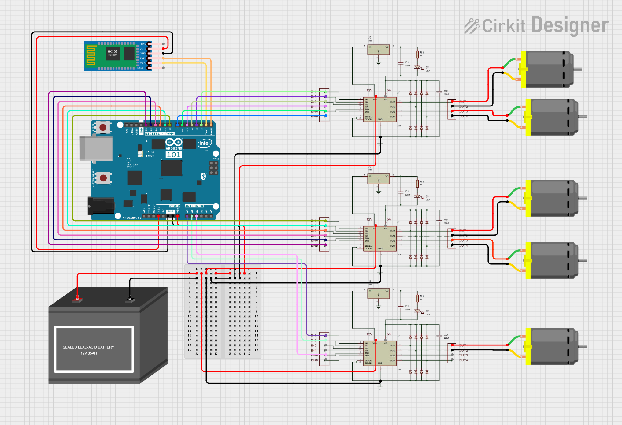
Circuit Documentation
Summary
This circuit is designed to control multiple DC motors using L298N motor drivers, which are interfaced with an Arduino 101 microcontroller. The Arduino 101 also connects to an HC-05 Bluetooth module for wireless communication. The entire system is powered by a 12V battery, which supplies power to the motor drivers and the Arduino 101. The motor drivers receive control signals from the Arduino to manage the direction and speed of the motors. The Bluetooth module allows for remote control capabilities via a Bluetooth-enabled device.
Component List
DC Motor
- Description: A standard DC motor used for converting electrical energy into mechanical rotation.
- Pins: pin 1, pin 2
L298N MOTOR DRIVER
- Description: A dual H-bridge motor driver capable of driving two DC motors or one stepper motor.
- Pins: IN1, IN2, IN3, IN4, ENA, ENB, OUT 1, OUT2, OUT3, OUT4, GND, 5V, 12V
Arduino 101
- Description: A microcontroller board based on the Intel Curie module, with built-in Bluetooth and sensor capabilities.
- Pins: A5/SCL, A4/SDA, AREF, GND, D13/SCK, D12/MISO, D11 PWM/MOSI, D10 PWM/SS, D9 PWM, D8, D7, D6 PWM, D5 PWM, D4, D3 PWM, D2, D1/TX, D0/RX, AIN, ioref, RESET, 3V3, 5V, VIN, A0, A1, A2, A3, ICSP MISO, ICSP SCK, ICSP MOSI
12V Battery (mini)
- Description: A compact 12V battery used to provide power to the circuit.
- Pins: -, +
HC-05 Bluetooth Module
- Description: A Bluetooth module for wireless communication with the Arduino.
- Pins: Key, VCC, GND, TXD, RXD, State
Wiring Details
DC Motor
- Motor 1:
- pin 1 connected to L298N MOTOR DRIVER OUT 1
- pin 2 connected to L298N MOTOR DRIVER OUT2
- Motor 2:
- pin 1 connected to L298N MOTOR DRIVER OUT3
- pin 2 connected to L298N MOTOR DRIVER OUT4
- Motor 3:
- pin 1 connected to L298N MOTOR DRIVER OUT 1
- pin 2 connected to L298N MOTOR DRIVER OUT2
- Motor 4:
- pin 1 connected to L298N MOTOR DRIVER OUT 1
- pin 2 connected to L298N MOTOR DRIVER OUT2
- Motor 5:
- pin 1 connected to L298N MOTOR DRIVER OUT3
- pin 2 connected to L298N MOTOR DRIVER OUT4
L298N MOTOR DRIVER
- Driver 1:
- 12V connected to 12V Battery (+) and Arduino 101 (VIN)
- GND connected to 12V Battery (-) and Arduino 101 (GND)
- ENA, IN1, IN2, IN3, IN4 connected to Arduino 101 (D6 PWM, D2, D3 PWM, D4, D5 PWM)
- OUT 1, OUT2, OUT3, OUT4 connected to DC Motors 1 and 2
- Driver 2:
- 12V connected to 12V Battery (+) and Arduino 101 (VIN)
- GND connected to 12V Battery (-) and Arduino 101 (GND)
- ENA, IN1, IN2 connected to Arduino 101 (A2, A0, A1)
- OUT 1, OUT2 connected to DC Motor 3
- Driver 3:
- 12V connected to 12V Battery (+) and Arduino 101 (VIN)
- GND connected to 12V Battery (-) and Arduino 101 (GND)
- ENA, ENB, IN1, IN2, IN3, IN4 connected to Arduino 101 (D12/MISO, D13/SCK, D8, D9 PWM, D10 PWM/SS, D11 PWM/MOSI)
- OUT 1, OUT2, OUT3, OUT4 connected to DC Motors 4 and 5
Arduino 101
- VIN connected to 12V Battery (+)
- GND connected to 12V Battery (-)
- Digital and analog pins connected to L298N MOTOR DRIVER control pins
- D1/TX connected to HC-05 Bluetooth Module (RXD)
- D0/RX connected to HC-05 Bluetooth Module (TXD)
- 3V3 connected to HC-05 Bluetooth Module (VCC)
- GND connected to HC-05 Bluetooth Module (GND)
12V Battery (mini)
- (+) connected to L298N MOTOR DRIVER (12V) and Arduino 101 (VIN)
- (-) connected to L298N MOTOR DRIVER (GND) and Arduino 101 (GND)
HC-05 Bluetooth Module
- VCC connected to Arduino 101 (3V3)
- GND connected to Arduino 101 (GND)
- TXD connected to Arduino 101 (D0/RX)
- RXD connected to Arduino 101 (D1/TX)
Documented Code
There is no code provided for the microcontroller. The documentation of the code would typically include a description of the functionality, setup, and loop sections, along with any functions or libraries used to control the motors and communicate with the Bluetooth module. Without the code, we cannot provide this section of the documentation.