
ESP32-Based Smart Power Monitoring System with Wi-Fi Connectivity
View and Edit Project In Cirkit Designer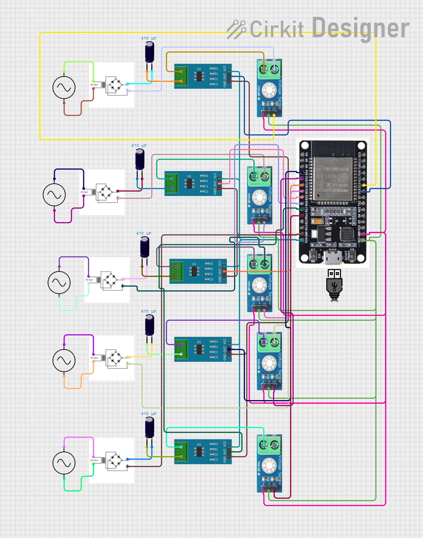
Circuit Documentation
Summary
This circuit involves an ESP32 microcontroller interfacing with multiple current and voltage sensors. The circuit also includes bridge rectifiers, AC supplies, and electrolytic capacitors. The ESP32 reads data from the sensors and processes it accordingly. The power supply for the sensors and the ESP32 is managed through the bridge rectifiers and capacitors.
Component List
ESP32
- Description: A powerful microcontroller with Wi-Fi and Bluetooth capabilities.
- Pins: EN, VP, VN, D34, D35, D32, D33, D25, D26, D27, D14, D12, D13, GND, VIN, 3V3, D15, D2, D4, RX2, TX2, D5, D18, D19, D21, RX0, TX0, D22, D23, BOOT
Bridge Rectifier
- Description: Converts AC to DC.
- Pins: AC input +, AC input -, +, -
AC Supply
- Description: Provides AC power.
- Pins: +ve, -ve
Electrolytic Capacitor
- Description: Stores electrical energy.
- Pins: -, +
- Properties:
- Capacitance: 0.00047 Farads
Current Sensor 5A
- Description: Measures current up to 5A.
- Pins: 1, 2, GND, OUT, VCC
Voltage Sensor DC 25V
- Description: Measures voltage up to 25V.
- Pins: +, -, output, gnd, vcc
USB Power
- Description: Provides power via USB.
- Pins: +, -
Wiring Details
ESP32
- D34 connected to OUT of Current Sensor 5A
- D35 connected to output of Voltage Sensor DC 25V
- D32 connected to OUT of Current Sensor 5A
- D33 connected to output of Voltage Sensor DC 25V
- D25 connected to OUT of Current Sensor 5A
- D26 connected to output of Voltage Sensor DC 25V
- D27 connected to OUT of Current Sensor 5A
- D14 connected to output of Voltage Sensor DC 25V
- GND connected to GND of all Current Sensors and Bridge Rectifier
- VIN connected to VCC of all Current Sensors
- 3V3 connected to + of all Voltage Sensors
Bridge Rectifier
- AC input + connected to +ve of AC Supply
- AC input - connected to -ve of AC Supply
- + connected to + of Electrolytic Capacitor
- - connected to GND of Voltage Sensor DC 25V
AC Supply
- +ve connected to AC input + of Bridge Rectifier
- -ve connected to AC input - of Bridge Rectifier
Electrolytic Capacitor
- + connected to + of Bridge Rectifier
- - connected to 2 of Current Sensor 5A
Current Sensor 5A
- OUT connected to D34, D32, D25, D27, D18 of ESP32
- GND connected to GND of ESP32 and other Current Sensors
- VCC connected to VIN of ESP32
- 1 connected to vcc of Voltage Sensor DC 25V
- 2 connected to - of Electrolytic Capacitor
Voltage Sensor DC 25V
- output connected to D35, D33, D26, D14, D19 of ESP32
- gnd connected to - of Bridge Rectifier
- vcc connected to 1 of Current Sensor 5A
- + connected to 3V3 of ESP32
- - connected to GND of ESP32
Code
No code provided for this circuit.
This documentation provides a comprehensive overview of the circuit, including a detailed list of components and their wiring connections. The ESP32 microcontroller interfaces with multiple current and voltage sensors, with power management handled by bridge rectifiers and capacitors.