
Arduino Mega 2560 with Multiple DHT Sensors for Environmental Monitoring
View and Edit Project In Cirkit Designer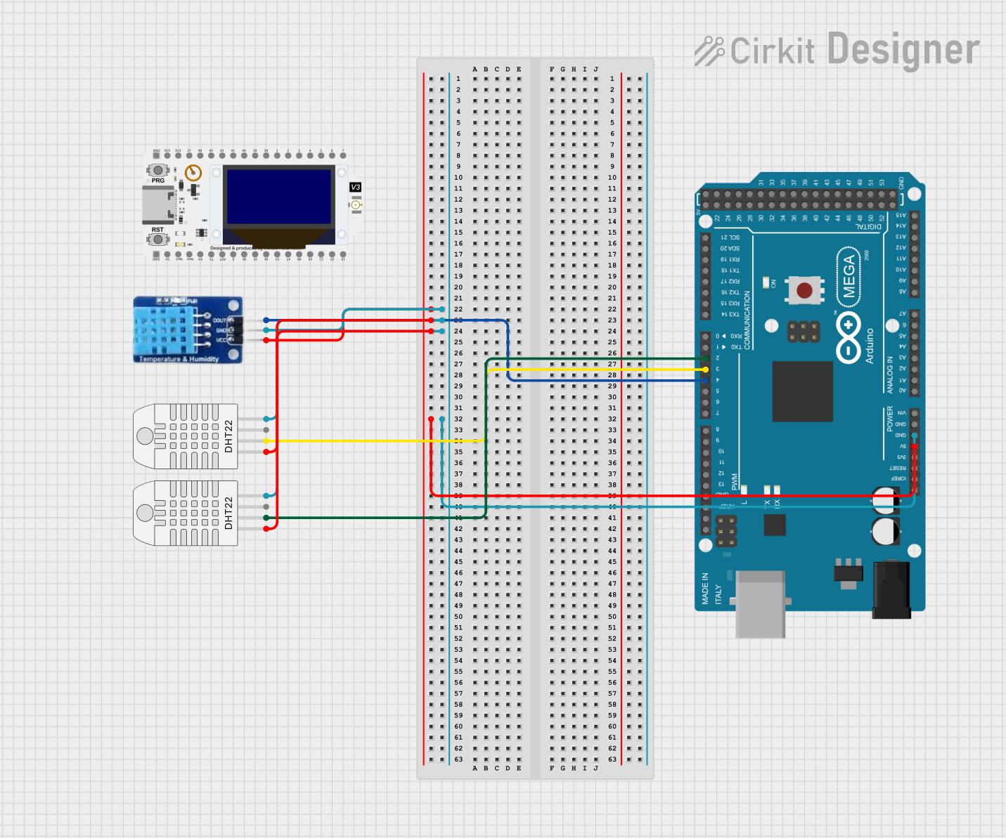
Circuit Documentation
Summary of the Circuit
This circuit integrates an Arduino Mega 2560 microcontroller with two types of temperature and humidity sensors: the DHT11 and DHT22. The sensors are powered by the 5V output from the Arduino and are grounded through the Arduino's GND pin. The data lines from the sensors are connected to specific digital pins on the Arduino, allowing for communication and data retrieval from the sensors. The circuit is designed to collect environmental data and can be expanded with additional code for processing and transmitting the collected data.
Component List
Arduino Mega 2560
- Description: A microcontroller board based on the ATmega2560, with a wide range of digital and analog I/O pins.
- Purpose: Acts as the central processing unit of the circuit, controlling the sensors and handling data.
DHT11
- Description: A basic, ultra low-cost digital temperature and humidity sensor.
- Purpose: Measures the ambient temperature and humidity.
DHT22 (Wokwi Compatible)
- Description: A more accurate digital temperature and humidity sensor compared to the DHT11.
- Purpose: Provides precise measurements of temperature and humidity.
WiFi Lora 32V3
- Description: A microcontroller with integrated Wi-Fi and LoRa capabilities.
- Purpose: Not directly used in the current circuit configuration but can be incorporated for wireless communication.
Wiring Details
Arduino Mega 2560
- 5V: Powers the DHT11 and both DHT22 sensors.
- GND: Common ground for the DHT11 and both DHT22 sensors.
- D2 PWM: Connected to the data pin (SDA) of one DHT22 sensor.
- D3 PWM: Connected to the data pin (SDA) of the other DHT22 sensor.
- D4 PWM: Connected to the data pin (DATA) of the DHT11 sensor.
DHT11
- DATA: Connected to digital pin D4 PWM on the Arduino Mega 2560.
- GND: Connected to the GND pin on the Arduino Mega 2560.
- VCC: Powered by the 5V pin on the Arduino Mega 2560.
DHT22 (Wokwi Compatible)
- SDA: One sensor's SDA pin is connected to digital pin D2 PWM, and the other to D3 PWM on the Arduino Mega 2560.
- GND: Both sensors share a common ground with the GND pin on the Arduino Mega 2560.
- VCC: Both sensors are powered by the 5V pin on the Arduino Mega 2560.
Documented Code
Arduino Mega 2560 - sketch.ino
void setup() {
  // put your setup code here, to run once:

}

void loop() {
  // put your main code here, to run repeatedly:

}
Note: The provided code is a template and does not include specific functionality. It should be expanded to initialize the sensors, read data from them, and handle the data accordingly.