
Arduino UNO Based Environmental Monitoring and Actuator Control System
View and Edit Project In Cirkit Designer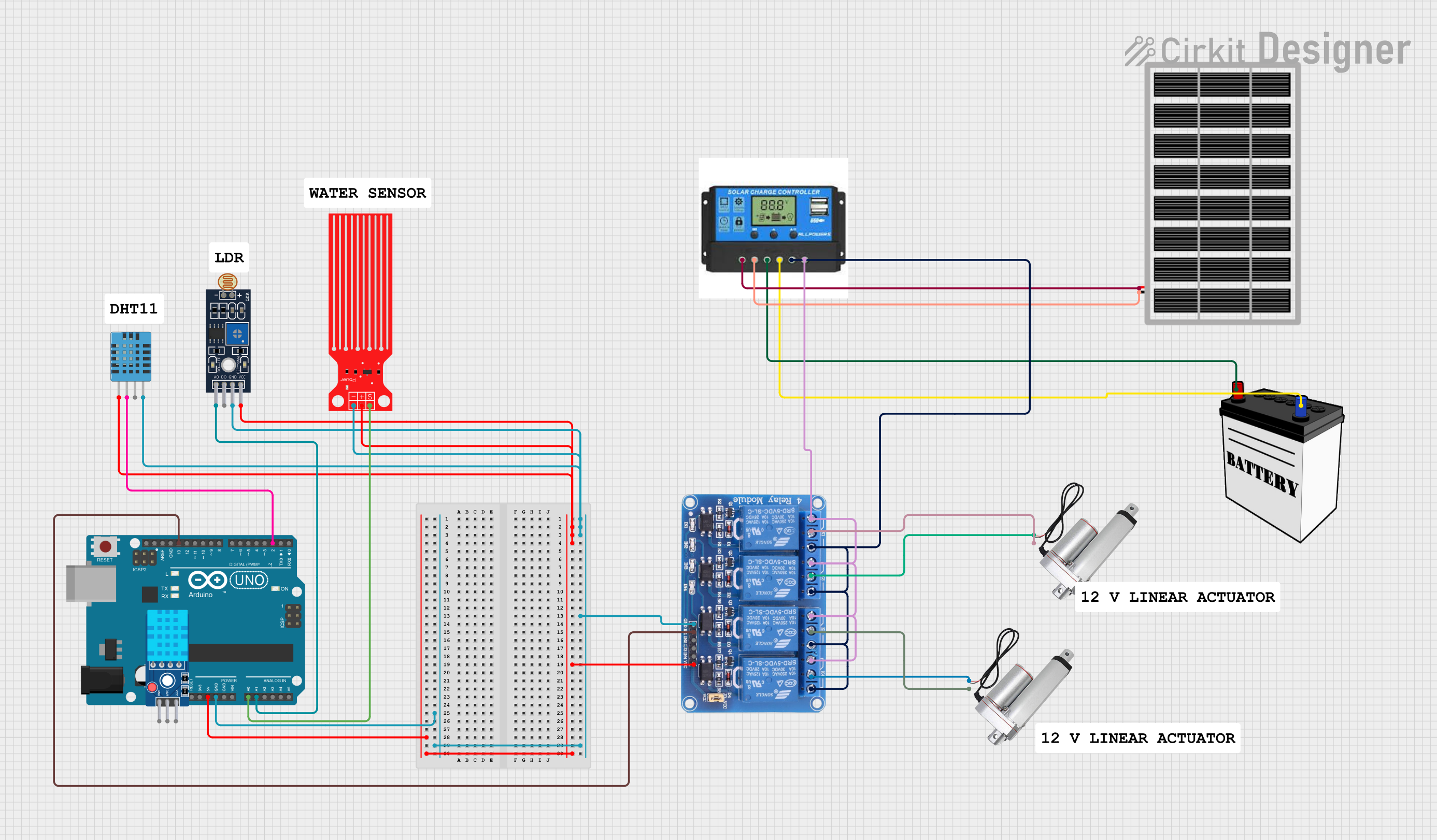
Circuit Documentation
Summary
This circuit is designed to interface various sensors and actuators with an Arduino UNO microcontroller. It includes environmental sensors, a relay module for controlling power to actuators, a charge controller for power management, and a battery for energy storage. The circuit is likely intended for an automated monitoring and control system, possibly for applications such as home automation, greenhouse management, or other IoT (Internet of Things) projects.
Component List
Arduino UNO
- Microcontroller board based on the ATmega328P
- It has 14 digital input/output pins, 6 analog inputs, a 16 MHz quartz crystal, a USB connection, a power jack, an ICSP header, and a reset button.
DHT11 Sensor V2
- A basic, ultra low-cost digital temperature and humidity sensor.
- It uses a capacitive humidity sensor and a thermistor to measure the surrounding air and outputs a digital signal on the data pin.
Water Level Sensor
- A simple water level sensor that can detect the presence of water.
- Outputs an analog signal that can be read by a microcontroller.
Linear Actuator
- An electromechanical device used for motion control, capable of pushing or pulling an object.
- Typically operated by a DC voltage.
DHT11 Humidity and Temperature Sensor
- A digital humidity and temperature sensor that provides calibrated digital output.
- It offers a proprietary serial interface for data transmission.
Relay 4 Channel 5v
- A 4-channel relay module that can be used to control high power/high voltage devices.
- Each channel can be individually triggered by a digital output from a microcontroller.
Charge Controller
- A device that regulates the voltage and current coming from the solar panels going to the battery.
- Ensures that the battery is charged properly and prevents overcharging.
12V Battery
- A storage device for electrical energy, typically used as a power source.
- Provides a voltage of 12V and can be recharged.
Sensor LDR LM393
- A light sensor module that includes an LDR (Light Dependent Resistor) and an LM393 comparator for producing a digital output.
- Can be used to detect the presence or absence of light.
Solar Panel
- A panel designed to absorb the sun's rays as a source of energy for generating electricity.
- Provides a clean and renewable source of energy.
Wiring Details
Arduino UNO
- GND connected to the common ground net.
- 5V connected to the common VCC net.
- A0 connected to Water Level Sensor SIG pin.
- A1 connected to Sensor LDR LM393 A0 pin.
- D2 connected to DHT11 Humidity and Temperature Sensor DATA pin.
- D13 connected to Relay 4 Channel 5v IN1 pin.
DHT11 Sensor V2
- GND connected to the common ground net.
- DAT not connected in the provided net list.
- VCC connected to the common VCC net.
Water Level Sensor
- SIG connected to Arduino UNO A0 pin.
- VCC connected to the common VCC net.
- GND connected to the common ground net.
Linear Actuator (Two Instances)
- + of one instance connected to Relay 4 Channel 5v COM2 pin.
- - of the same instance connected to Relay 4 Channel 5v COM1 pin.
- + of the other instance connected to Relay 4 Channel 5v COM4 pin.
- - of the other instance connected to Relay 4 Channel 5v COM3 pin.
DHT11 Humidity and Temperature Sensor
- VDD connected to the common VCC net.
- DATA connected to Arduino UNO D2 pin.
- GND connected to the common ground net.
Relay 4 Channel 5v
- GND connected to the common ground net.
- VCC connected to the common VCC net.
- IN1 connected to Arduino UNO D13 pin.
- COM1, COM2, COM3, COM4 connected to Linear Actuators.
- NO1, NO2, NO3, NO4 connected to Charge Controller Load Positive.
- NC1, NC2, NC3, NC4 connected to Charge Controller Load Negative.
Charge Controller
- Solar Positive connected to Solar Panel vcc.
- Solar Negative connected to Solar Panel gnd.
- Battery Positive connected to 12V Battery VCC.
- Battery Negative connected to 12V Battery GND.
- Load Positive connected to Relay 4 Channel 5v NO1, NO2, NO3, NO4.
- Load Negative connected to Relay 4 Channel 5v NC1, NC2, NC3, NC4.
12V Battery
- VCC connected to Charge Controller Battery Positive.
- GND connected to Charge Controller Battery Negative.
Sensor LDR LM393
- A0 connected to Arduino UNO A1 pin.
- D0 not connected in the provided net list.
- GND connected to the common ground net.
- VCC connected to the common VCC net.
Solar Panel
- vcc connected to Charge Controller Solar Positive.
- gnd connected to Charge Controller Solar Negative.
Documented Code
Arduino UNO Code (sketch.ino)
void setup() {
  // put your setup code here, to run once:

}

void loop() {
  // put your main code here, to run repeatedly:

}
Note: The provided code for the Arduino UNO is a template with empty setup and loop functions. Actual implementation code is required for the circuit to perform any meaningful operation.