
Solar-Powered Smart Sensor System with Arduino and ESP32-CAM
View and Edit Project In Cirkit Designer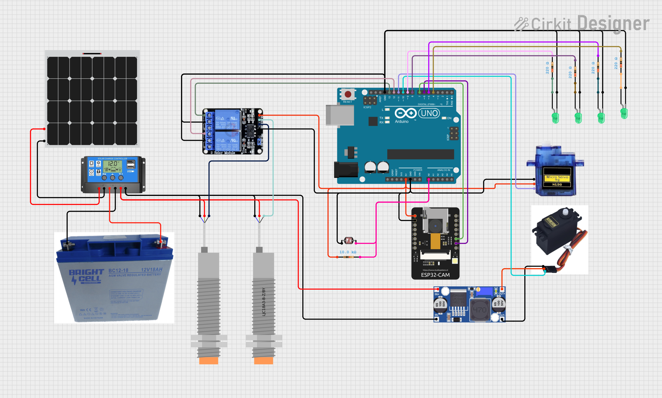
Circuit Documentation
Summary
This circuit is designed to manage and monitor a solar power system. It includes a solar charge controller, solar panel, battery, various sensors, relays, servos, and microcontrollers. The system is capable of charging a battery from a solar panel, controlling loads, and monitoring environmental conditions using sensors. The Arduino UNO and ESP32-CAM microcontrollers are used for control and monitoring purposes.
Component List
Solar Charge Controller
- Description: Manages the charging of the battery from the solar panel and controls the load.
- Pins: Solar Cell +, Solar Cell -, Battery +, Battery -, Load +, Load -
Solar Panel
- Description: Converts sunlight into electrical energy.
- Pins: +, -
Arduino UNO
- Description: Microcontroller used for control and monitoring.
- Pins: UNUSED, IOREF, Reset, 3.3V, 5V, GND, Vin, A0, A1, A2, A3, A4, A5, SCL, SDA, AREF, D13, D12, D11, D10, D9, D8, D7, D6, D5, D4, D3, D2, D1, D0
LJ18A3-H-ZBX Inductive Proximity Sensor
- Description: Detects the presence of metal objects.
- Pins: VO (BLU), VI (BRN), SIG (BLK)
LJC18A3-B-Z/BY Capacitive Proximity Sensor
- Description: Detects the presence of non-metal objects.
- Pins: VO (BLU), VI (BRN), SIG (BLK)
Two Channel Relay 5v
- Description: Controls high voltage devices using low voltage signals.
- Pins: VCC, IN2, IN1, GND, NC2, C2, NO2, NC1, C1, NO1
ESP32 - CAM
- Description: Microcontroller with camera capabilities.
- Pins: 5V, GND, IO12, IO13, IO15, IO14, IO2, IO4, VOT, VOR, VCC, IO0, IO16, 3V3
Photocell (LDR)
- Description: Light-dependent resistor used to detect light levels.
- Pins: pin 0, pin 1
Resistor (10k Ohms)
- Description: Limits current flow.
- Pins: pin1, pin2
Buck Converter
- Description: Steps down voltage from a higher level to a lower level.
- Pins: IN+, IN-, OUT+, OUT-
Micro Servo 9G
- Description: Small servo motor for precise control.
- Pins: GND, +5V, PWM
SG5010 Servo
- Description: Standard servo motor for precise control.
- Pins: GND, VCC, Signal
LED: Two Pin (green)
- Description: Light-emitting diode for visual indication.
- Pins: cathode, anode
Resistor (220 Ohms)
- Description: Limits current flow.
- Pins: pin1, pin2
BC12-18Ah Battery
- Description: Stores electrical energy for later use.
- Pins: -, +
Wiring Details
Solar Charge Controller
- Solar Cell + connected to Solar Panel +
- Solar Cell - connected to Solar Panel -
- Battery + connected to Battery +
- Battery - connected to Battery -
- Load + connected to VI (BRN) of LJ18A3-H-ZBX Inductive Proximity Sensor, VI (BRN) of LJC18A3-B-Z/BY Capacitive Proximity Sensor, and IN+ of Buck Converter
- Load - connected to VO (BLU) of LJ18A3-H-ZBX Inductive Proximity Sensor, VO (BLU) of LJC18A3-B-Z/BY Capacitive Proximity Sensor, and IN- of Buck Converter
Solar Panel
- + connected to Solar Cell + of Solar Charge Controller
- - connected to Solar Cell - of Solar Charge Controller
Arduino UNO
- 5V connected to VCC of Two Channel Relay 5v, 5V of ESP32 - CAM, +5V of Micro Servo 9G, and pin1 of 10k Ohms Resistor
- GND connected to GND of Two Channel Relay 5v, GND of ESP32 - CAM, pin 0 of Photocell (LDR), GND of Micro Servo 9G, and cathode of LED: Two Pin (green)
- A0 connected to pin 1 of Photocell (LDR) and pin2 of 10k Ohms Resistor
- D13 connected to NC2 of Two Channel Relay 5v
- D12 connected to NC1 of Two Channel Relay 5v
- D11 connected to PWM of Micro Servo 9G
- D10 connected to Signal of SG5010 Servo
- D9 connected to pin2 of 220 Ohms Resistor
- D8 connected to pin2 of 220 Ohms Resistor
- D7 connected to VOR of ESP32 - CAM
- D6 connected to VOT of ESP32 - CAM
- D5 connected to pin2 of 220 Ohms Resistor
- D4 connected to pin2 of 220 Ohms Resistor
LJ18A3-H-ZBX Inductive Proximity Sensor
- VI (BRN) connected to Load + of Solar Charge Controller
- VO (BLU) connected to Load - of Solar Charge Controller
- SIG (BLK) connected to IN1 of Two Channel Relay 5v
LJC18A3-B-Z/BY Capacitive Proximity Sensor
- VI (BRN) connected to Load + of Solar Charge Controller
- VO (BLU) connected to Load - of Solar Charge Controller
- SIG (BLK) connected to IN2 of Two Channel Relay 5v
Two Channel Relay 5v
- VCC connected to 5V of Arduino UNO
- GND connected to GND of Arduino UNO
- IN1 connected to SIG (BLK) of LJ18A3-H-ZBX Inductive Proximity Sensor
- IN2 connected to SIG (BLK) of LJC18A3-B-Z/BY Capacitive Proximity Sensor
- NC2 connected to D13 of Arduino UNO
- NC1 connected to D12 of Arduino UNO
- C2 connected to cathode of LED: Two Pin (green)
- C1 connected to cathode of LED: Two Pin (green)
ESP32 - CAM
- 5V connected to VCC of Two Channel Relay 5v
- GND connected to GND of Two Channel Relay 5v
- VOR connected to D7 of Arduino UNO
- VOT connected to D6 of Arduino UNO
Photocell (LDR)
- pin 0 connected to GND of Arduino UNO
- pin 1 connected to A0 of Arduino UNO
Resistor (10k Ohms)
- pin1 connected to 5V of Arduino UNO
- pin2 connected to A0 of Arduino UNO
Buck Converter
- IN+ connected to Load + of Solar Charge Controller
- IN- connected to Load - of Solar Charge Controller
- OUT+ connected to VCC of SG5010 Servo
- OUT- connected to GND of SG5010 Servo
Micro Servo 9G
- GND connected to GND of Arduino UNO
- +5V connected to 5V of Arduino UNO
- PWM connected to D11 of Arduino UNO
SG5010 Servo
- GND connected to OUT- of Buck Converter
- VCC connected to **