Arduino UNO Controlled Robot with MPU-6050 and NRF24L01 Wireless Communication
Circuit Documentation
Summary
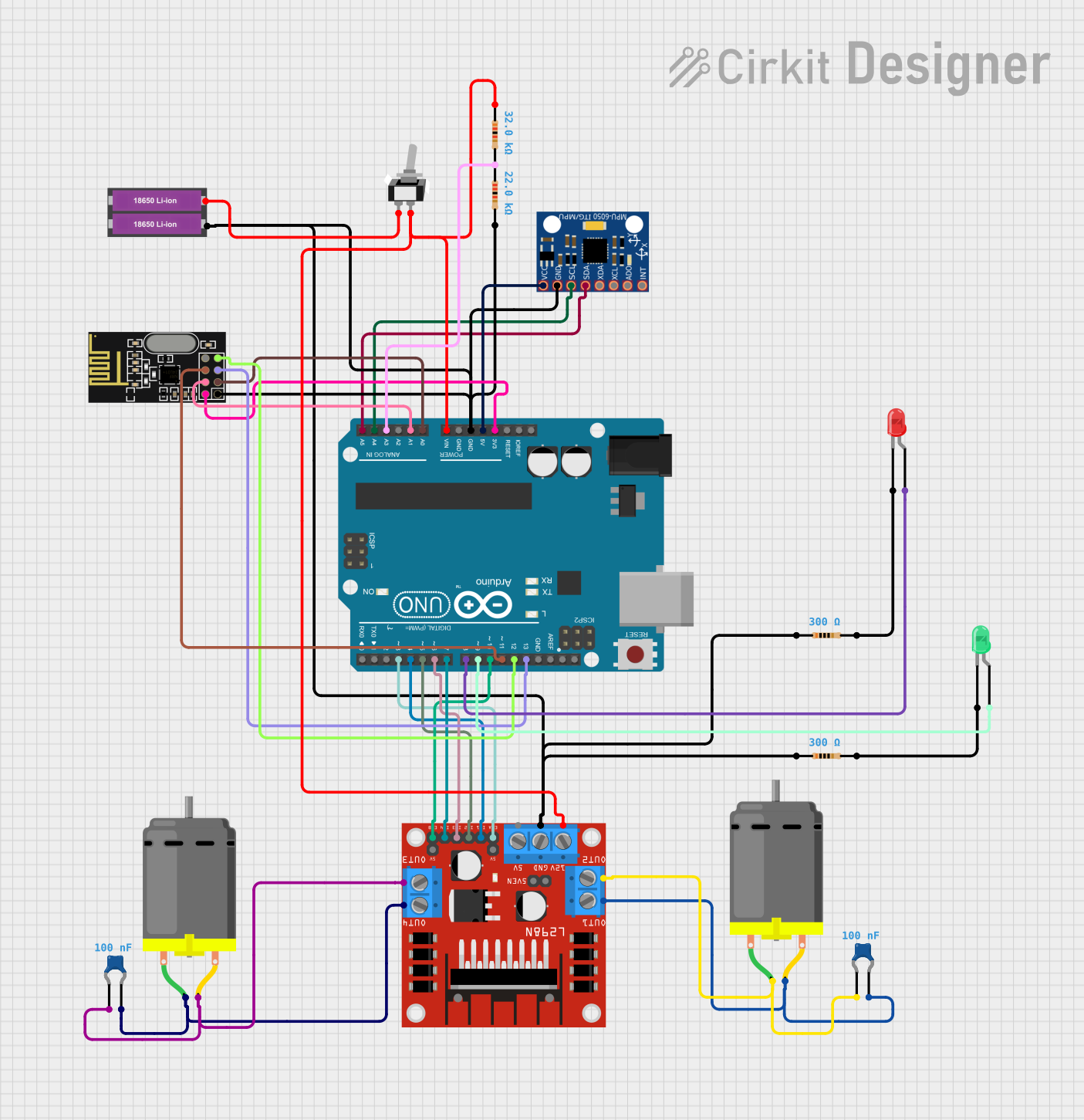
This document provides a detailed overview of a circuit that includes an Arduino UNO microcontroller, an L298N DC motor driver, two DC motors, an MPU-6050 accelerometer and gyroscope module, an NRF24L01 wireless communication module, a toggle switch, a power source consisting of two 18650 Li-ion batteries, two LEDs (one red, one green), and various resistors and ceramic capacitors. The circuit is designed to control the DC motors while monitoring orientation via the MPU-6050 and communicating wirelessly using the NRF24L01 module. The Arduino UNO serves as the central processing unit, interfacing with the sensors, motor driver, and communication module.
Component List
- Arduino UNO: A microcontroller board based on the ATmega328P, featuring digital and analog I/O pins.
- L298N DC Motor Driver: A module capable of driving two DC motors or one stepper motor.
- DC Motor (x2): Electric motors that convert electrical energy into mechanical rotation.
- MPU-6050: A motion processing module that contains a 3-axis accelerometer and a 3-axis gyroscope.
- NRF24L01: A wireless communication module operating in the 2.4GHz band.
- Toggle Switch (SPST): A single-pole single-throw switch used to control the power flow in a circuit.
- 18650 Li-ion Battery (x2): Rechargeable batteries providing the power source for the circuit.
- LED (Red): A red light-emitting diode used as an indicator.
- LED (Green): A green light-emitting diode used as an indicator.
- Resistor (x4): Passive components used to limit current or divide voltages. Their values are 300 Ohms (x2), 32k Ohms, and 22k Ohms.
- Ceramic Capacitor (x2): Passive components used to store energy in an electric field, with a capacitance of 0.1 µF each.
Wiring Details
Arduino UNO
- 3.3V to NRF24L01 VCC (3V)
- 5V to MPU-6050 VCC
- GND to NRF24L01 GND, Resistor (300 Ohms), Resistor (22k Ohms), Resistor (300 Ohms), 18650 Li-ion Battery (-), L298N DC motor driver GND, MPU-6050 GND
- Vin to Toggle Switch COM, Resistor (32k Ohms), L298N DC motor driver 12V
- A0 to NRF24L01 CE
- A1 to NRF24L01 CSN
- A3 to Resistor (22k Ohms)
- A4 to MPU-6050 SCL
- A5 to MPU-6050 SDA
- D13 to NRF24L01 SCK
- D12 to NRF24L01 MISO
- D11 to NRF24L01 MOSI
- D10 to L298N DC motor driver ENB
- D9 to Green LED anode
- D8 to Red LED anode
- D7 to L298N DC motor driver IN4
- D6 to L298N DC motor driver IN3
- D5 to L298N DC motor driver IN2
- D4 to L298N DC motor driver IN1
- D3 to L298N DC motor driver ENA
L298N DC Motor Driver
- OUT1 to DC Motor 1 pin 2, Ceramic Capacitor 1 pin 1
- OUT2 to DC Motor 1 pin 1, Ceramic Capacitor 1 pin 0
- OUT3 to DC Motor 2 pin 2, Ceramic Capacitor 2 pin 0
- OUT4 to DC Motor 2 pin 1, Ceramic Capacitor 2 pin 1
DC Motor (x2)
- Motor 1 pin 1 to L298N DC motor driver OUT2, Ceramic Capacitor 1 pin 0
- Motor 1 pin 2 to L298N DC motor driver OUT1, Ceramic Capacitor 1 pin 1
- Motor 2 pin 1 to L298N DC motor driver OUT4, Ceramic Capacitor 2 pin 1
- Motor 2 pin 2 to L298N DC motor driver OUT3, Ceramic Capacitor 2 pin 0
Toggle Switch (SPST)
- COM to Arduino UNO Vin, Resistor (32k Ohms), L298N DC motor driver 12V
- L1 to 18650 Li-ion Battery (+)
LEDs
- Red LED anode to Arduino UNO D8
- Red LED cathode to Resistor (300 Ohms) pin 2
- Green LED anode to Arduino UNO D9
- Green LED cathode to Resistor (300 Ohms) pin 2
Resistors
- 300 Ohms between Red LED cathode and Arduino GND
- 300 Ohms between Green LED cathode and Arduino GND
- 32k Ohms between Toggle Switch COM and Arduino Vin
- 22k Ohms between Arduino A3 and GND
Ceramic Capacitors
- 0.1 µF across the terminals of each DC Motor
Documented Code
Arduino UNO Code (sketch.ino)
void setup() {
  // put your setup code here, to run once:

}

void loop() {
  // put your main code here, to run repeatedly:

}
Note: The provided code is a template and does not contain any functional code. It is expected that the user will fill in the setup and loop functions with code to control the motors, read sensor data, and handle wireless communication.