Arduino Nano-Based Ultrasonic Distance-Controlled Relay for 12V LED
Circuit Documentation
Summary
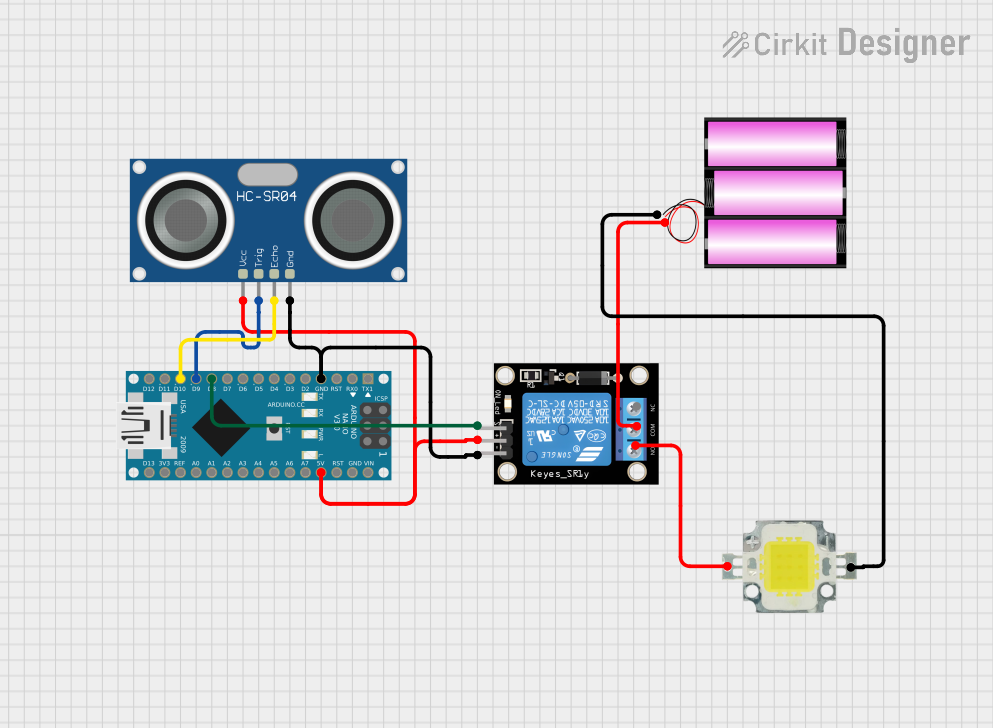
This circuit is designed to control a 12V Power LED using an Arduino Nano and an HC-SR04 Ultrasonic Sensor. The LED is powered by a 12V battery and is controlled via a relay module. The ultrasonic sensor measures the distance to an object, and if the object is within a specified safety distance, the relay is triggered to turn off the LED.
Component List
Arduino Nano
- Description: A small, complete, and breadboard-friendly board based on the ATmega328P.
- Pins: D1/TX, D0/RX, RESET, GND, D2, D3, D4, D5, D6, D7, D8, D9, D10, D11/MOSI, D12/MISO, VIN, 5V, A7, A6, A5, A4, A3, A2, A1, A0, AREF, 3V3, D13/SCK
HC-SR04 Ultrasonic Sensor
- Description: A sensor used to measure distance by using ultrasonic waves.
- Pins: VCC, TRIG, ECHO, GND
Relay Module 1 Channel
- Description: A module used to control high voltage devices with a low voltage signal.
- Pins: S, 5V, GND, NC, COM, NO
Battery 12V
- Description: A 12V battery used to power the LED.
- Pins: +, -
Power LED 12V 10W 0.8-0.9A
- Description: A high-power LED that operates at 12V.
- Pins: +, -
Wiring Details
Arduino Nano
GND is connected to:
- GND of Relay Module 1 Channel
- GND of HC-SR04 Ultrasonic Sensor
D8 is connected to:
- S of Relay Module 1 Channel
D9 is connected to:
- TRIG of HC-SR04 Ultrasonic Sensor
D10 is connected to:
- ECHO of HC-SR04 Ultrasonic Sensor
5V is connected to:
- 5V of Relay Module 1 Channel
- VCC of HC-SR04 Ultrasonic Sensor
HC-SR04 Ultrasonic Sensor
GND is connected to:
- GND of Arduino Nano
- GND of Relay Module 1 Channel
TRIG is connected to:
- D9 of Arduino Nano
ECHO is connected to:
- D10 of Arduino Nano
VCC is connected to:
- 5V of Arduino Nano
- 5V of Relay Module 1 Channel
Relay Module 1 Channel
GND is connected to:
- GND of Arduino Nano
- GND of HC-SR04 Ultrasonic Sensor
S is connected to:
- D8 of Arduino Nano
5V is connected to:
- 5V of Arduino Nano
- VCC of HC-SR04 Ultrasonic Sensor
COM is connected to:
- of Battery 12V
NO is connected to:
- of Power LED 12V 10W 0.8-0.9A
Battery 12V
+ is connected to:
- COM of Relay Module 1 Channel
- is connected to:
- of Power LED 12V 10W 0.8-0.9A
Power LED 12V 10W 0.8-0.9A
+ is connected to:
- NO of Relay Module 1 Channel
- is connected to:
- of Battery 12V
Code Documentation
const int trigPin = 9;
const int echoPin = 10;
const int relayPin = 8;
const int safetyDistance = 100;  // Distance in cm (1 meter)

void setup() {
  pinMode(trigPin, OUTPUT);
  pinMode(echoPin, INPUT);
  pinMode(relayPin, OUTPUT);
  digitalWrite(relayPin, LOW);  // Keep TV on initially
  Serial.begin(9600);
}

void loop() {
  long duration, distance;
  digitalWrite(trigPin, LOW);
  delayMicroseconds(2);
  digitalWrite(trigPin, HIGH);
  delayMicroseconds(10);
  digitalWrite(trigPin, LOW);

  duration = pulseIn(echoPin, HIGH);
  distance = (duration * 0.034) / 2;

  Serial.print("Distance: ");
  Serial.println(distance);

  if (distance <= safetyDistance) {
    digitalWrite(relayPin, HIGH);  // Turn off TV
  } else {
    digitalWrite(relayPin, LOW);  // Keep TV on
  }

  delay(500);  // Delay for stability
}
This code is designed to control the relay based on the distance measured by the HC-SR04 Ultrasonic Sensor. If the measured distance is less than or equal to the safety distance (100 cm), the relay is triggered to turn off the LED. Otherwise, the LED remains on.