Arduino UNO Based Environmental Monitoring System with LCD Feedback
Circuit Documentation
Summary
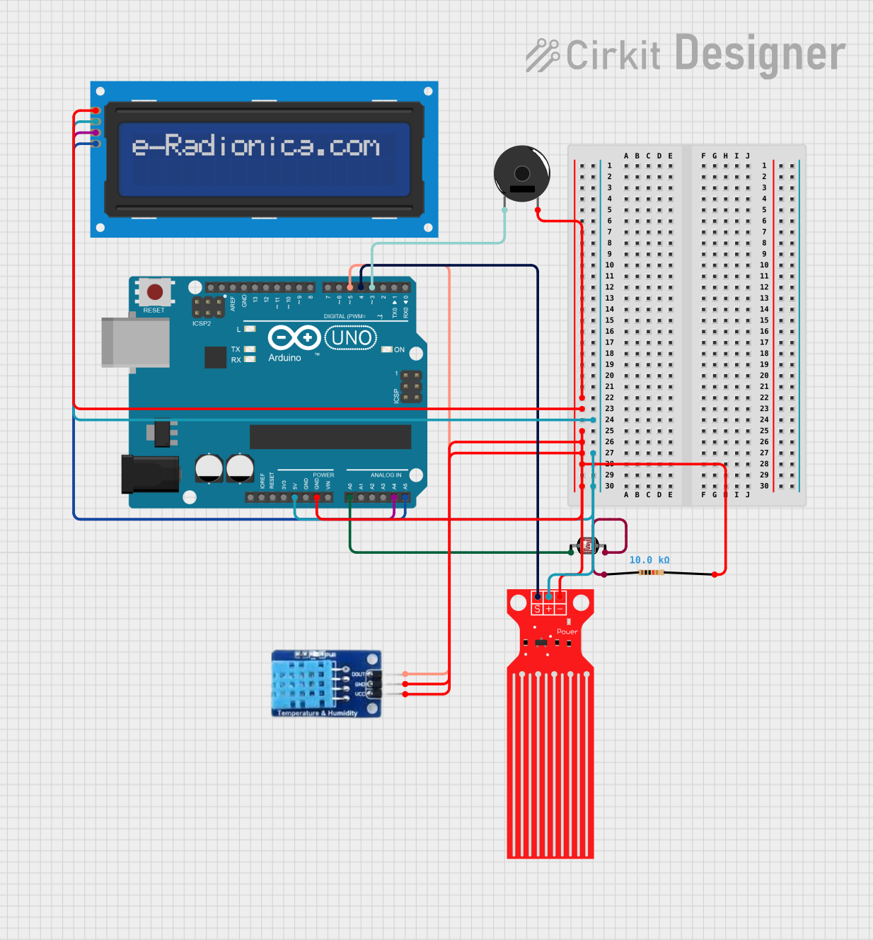
This circuit is designed to monitor environmental conditions and provide alerts through a buzzer and an LCD display. It includes an Arduino UNO microcontroller, a DHT11 temperature and humidity sensor, a photocell (LDR) for light sensing, a water level sensor, a piezo buzzer for audible alerts, and an LCD screen with I2C interface for visual feedback. The circuit is likely used for monitoring plant growth conditions, such as light intensity, temperature, humidity, and water level, and alerting the user when these parameters are outside of the desired range.
Component List
Arduino UNO
- Microcontroller board based on the ATmega328P
- Provides digital and analog I/O pins
- Powers the circuit and processes sensor data
DHT11
- Digital temperature and humidity sensor
- Provides ambient temperature and humidity readings
Photocell (LDR)
- Light-dependent resistor
- Changes resistance based on the light intensity
Water Level Sensor
- Detects the presence of water
- Provides digital output indicating water level conditions
Piezo Buzzer
- Emits an audible alert when activated
- Used for indicating alarm conditions
LCD screen 16x2 I2C
- Displays text on a 16x2 character screen
- Uses I2C communication for interfacing with the Arduino
Resistor (10k Ohms)
- Limits current or divides voltage
- Used in conjunction with the photocell (LDR)
Wiring Details
Arduino UNO
5Vpin provides power to the LCD screen and Water Level SensorGNDpin is connected to the common ground netA0pin is connected to the Photocell (LDR)A4(SDA) andA5(SCL) pins are connected to the LCD screen for I2C communicationD3pin is connected to the Piezo BuzzerD4pin is connected to the Water Level Sensor signal pinD5pin is connected to the DHT11 data pin
DHT11
DATApin connected to Arduino pinD5VCCandGNDpins connected to power and common ground respectively
Photocell (LDR)
- One pin connected to Arduino pin
A0 - Other pin connected to one end of the 10k Ohm Resistor
Water Level Sensor
SIGpin connected to Arduino pinD4VCCandGNDpins connected to power and common ground respectively
Piezo Buzzer
- One pin connected to Arduino pin
D3 - Other pin connected to common ground
LCD screen 16x2 I2C
SCLandSDApins connected to Arduino pinsA5andA4respectivelyVCCpin connected to 5V power from the ArduinoGNDpin connected to common ground
Resistor (10k Ohms)
- One pin connected to the Photocell (LDR)
- Other pin connected to common ground
Documented Code
#include <Arduino.h>
#include <DHT.h>
#include <Wire.h>
#include <LiquidCrystal_I2C.h>

// Define pins
const int lightSensorPin = A0;
const int buzzerPin = 3;
const int waterLevelSensorPin = 4;
const int dhtPin = 5;

// LCD setup (I2C address 0x27 is common, check your LCD address)
LiquidCrystal_I2C lcd(0x27, 16, 2);

// DHT sensor setup (DHT22 or DHT11)
#define DHTTYPE DHT11
DHT dht(dhtPin, DHTTYPE);

// Set thresholds for Chinese Money Plant
const int lightHighThreshold = 800;  // Too much light (bright direct light)
const int lightLowThreshold = 300;   // Too little light (dim light)
const float tempHighThreshold = 30.0; // Max temperature (too hot)
const float tempLowThreshold = 18.0;  // Min temperature (too cold)
const int waterLevelHighThreshold = 1;  // Water sensor detects high water level (overwatering)
const int waterLevelLowThreshold = 0;   // Water sensor detects low water level (underwatering)
const unsigned long buzzerDuration = 1000; // Buzzer on duration

bool isAlarmActive = false;
unsigned long buzzerStartTime = 0;

void setup() {
  pinMode(lightSensorPin, INPUT);
  pinMode(buzzerPin, OUTPUT);
  pinMode(waterLevelSensorPin, INPUT);

  dht.begin();
  lcd.init();  // Initialize the LCD
  lcd.backlight();  // Turn on the LCD backlight

  Serial.begin(9600);
  lcd.clear();  // Ensure the LCD is cleared on startup
}

void loop() {
  // Read sensor values
  int lightValue = analogRead(lightSensorPin);
  float temperature = dht.readTemperature();
  int waterLevel = digitalRead(waterLevelSensorPin);

  // Print sensor values for debugging
  Serial.print("Light: ");
  Serial.println(lightValue);
  Serial.print("Temperature: ");
  Serial.println(temperature);
  Serial.print("Water Level: ");
  Serial.println(waterLevel);

  // Check for errors and alarms
  bool errorCondition = false;
  String errorMessage = "";

  // Light intensity check
  if (lightValue > lightHighThreshold) {
    errorMessage = "Too much light!";
    errorCondition = true;
  } else if (lightValue < lightLowThreshold) {
    errorMessage = "Too little light!";
    errorCondition = true;
  }

  // Temperature check
  if (temperature > tempHighThreshold) {
    errorMessage = "Temp too high!";
    errorCondition = true;
  } else if (temperature < tempLowThreshold) {
    errorMessage = "Temp too low!";
    errorCondition = true;
  }

  // Water level check
  if (waterLevel == waterLevelHighThreshold) {
    errorMessage = "Water too high!";
    errorCondition = true;
  } else if (waterLevel == waterLevelLowThreshold) {
    errorMessage = "Water too low!";
    errorCondition = true;
  }

  // Activate alarm if an error condition is detected
  if (errorCondition) {
    activateAlarm(errorMessage, lightValue, temperature, waterLevel);
  } else {
    deactivateAlarm();
  }
}

// Function to activate alarm and show on LCD
void activateAlarm(String errorMessage, int lightValue, float temperature, int waterLevel) {
  if (!isAlarmActive) {
    isAlarmActive = true;
    buzzerStartTime = millis();
    Serial.println("Alarm activated: " + errorMessage);
    lcd.clear();  // Clear the LCD to show the new message
  }

  // Keep the buzzer on for the specified duration
  if (millis() - buzzerStartTime < buzzerDuration) {
    digitalWrite(buzzerPin, HIGH);

    // Display alarm message and sensor values on the LCD
    lcd.setCursor(0, 0);
    lcd.print("ALARM: ");
    lcd.print(errorMessage);

    // Display light and temperature values on the second line
    lcd.setCursor(0, 1);
    lcd.print("L:");
    lcd.print(lightValue);
    lcd.print(" T:");
    lcd.print(temperature);
    lcd.print("C");
  } else {
    digitalWrite(buzzerPin, LOW);
    isAlarmActive = false;
  }
}

// Function to deactivate alarm and clear LCD
void deactivateAlarm() {
  if (isAlarmActive) {
    digitalWrite(buzzerPin, LOW);
    isAlarmActive = false;
    lcd.clear();  // Clear the LCD when no alarm is active
  }
}
This code is responsible for reading sensor data, determining if any of the readings are outside of the predefined thresholds, and then activating an alarm if necessary. The alarm consists of an audible alert from the buzzer and a visual message on the LCD screen. The code also includes debugging outputs to the serial monitor for monitoring sensor values.