
ESP32 and Raspberry Pi 3B IoT Device with Display and Audio Monitoring
View and Edit Project In Cirkit Designer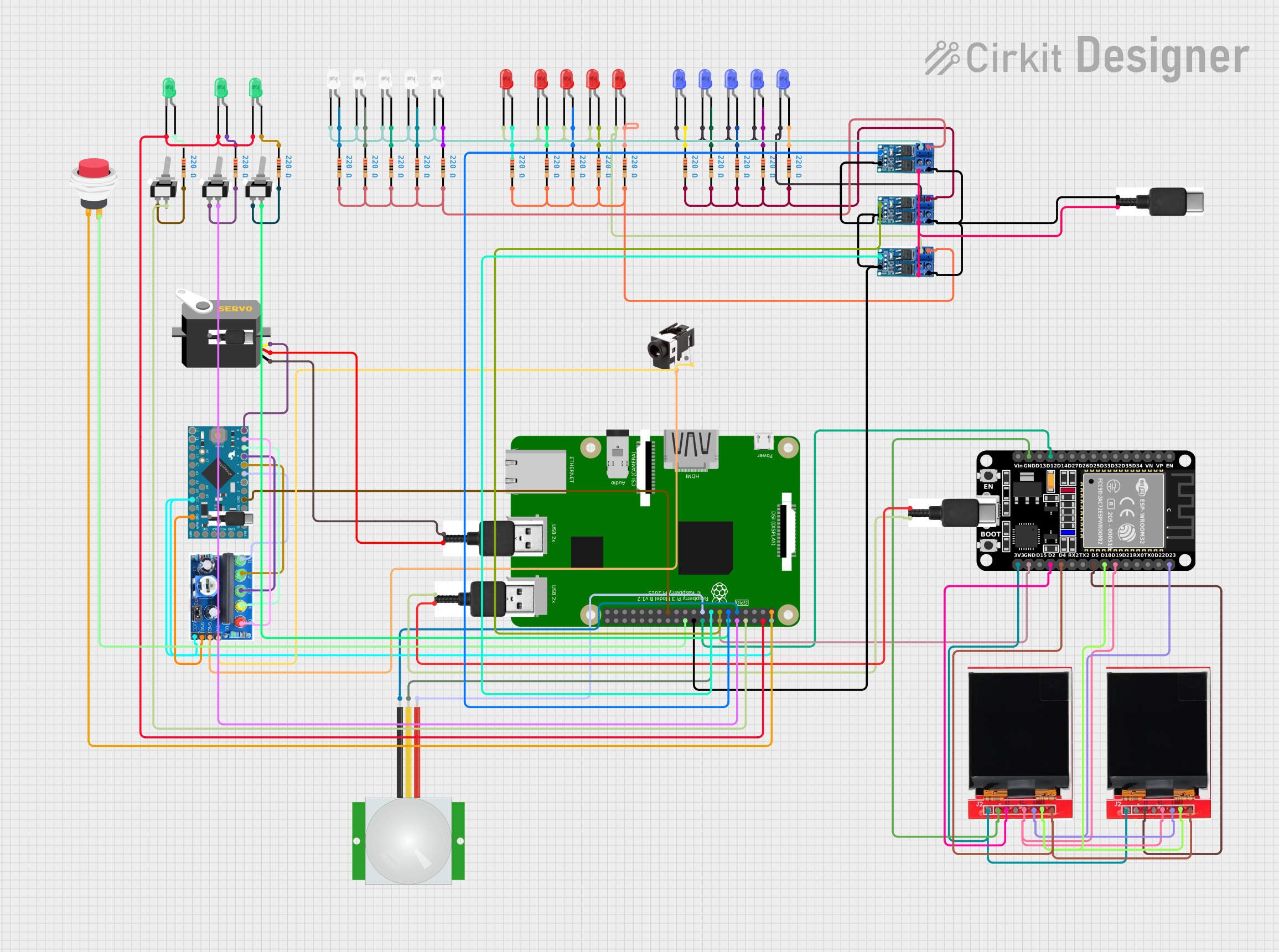
Circuit Documentation
Summary
This document provides a detailed overview of a circuit that includes a variety of components such as microcontrollers (ESP32 and Raspberry Pi 3B), sensors (PIR sensor), displays (TFT LCD Display ST7735S), audio components (Stereo Jack, Audio Level Meter), actuators (Servo), and various other components like LEDs, resistors, and switches. The circuit is designed to interface between the ESP32 and Raspberry Pi 3B, with the ESP32 handling peripheral devices like displays and sensors, while the Raspberry Pi 3B manages input/output control and power management through MOSFETs (XY MOS). The circuit also includes user interface elements such as push switches and toggle switches.
Component List
- ESP32 (30 pin): A microcontroller with Wi-Fi and Bluetooth capabilities, featuring a variety of digital I/O pins.
- Raspberry Pi 3B: A single-board computer with GPIO pins used for interfacing with various components.
- PIR sensor: A motion sensor that detects changes in infrared levels caused by movement.
- TFT LCD Display ST7735S: A small graphical display for visual output.
- Audio Level Meter: A device that indicates the level of an audio signal.
- Servo: An actuator that can be positioned with PWM signals.
- Stereo Jack: An audio connector for input/output audio signals.
- Toggle Switch spst: A single-pole single-throw switch used for controlling power or signal flow.
- USB-C & USB: Connectors for power supply and data transfer.
- Arduino Pro Mini: A compact microcontroller board based on the ATmega328.
- XY MOS: A MOSFET module used for switching high-power devices.
- LEDs: Light Emitting Diodes used as indicators.
- Resistors: Components used to limit current or divide voltages in the circuit.
- 2Pin Push Switch: A momentary switch that connects two pins when pressed.
Wiring Details
ESP32 (30 pin)
EN,VP,VN,D34,D35,D32,D33,D25,D26,D27,D14,TX0,RX0,D21,D19,TX2,RX2,D15,3V3: Not connected in this circuit.D12: Connected to Raspberry Pi 3B GPIO24.GND: Common ground with TFT LCD Display ST7735S and Raspberry Pi 3B.Vin: Not connected in this circuit.D23: Connected to TFT LCD Display ST7735S SDA.D22,TX0,RX0: Not connected in this circuit.D21: Not connected in this circuit.D19: Connected to TFT LCD Display ST7735S A0.D18: Connected to TFT LCD Display ST7735S SCK.D5: Connected to TFT LCD Display ST7735S CS.D4: Connected to TFT LCD Display ST7735S LED.D2: Connected to TFT LCD Display ST7735S CS.
Raspberry Pi 3B
3v3: Connected to PIR sensor VDD and 2Pin Push Switch Input +.GPIO2,GPIO3,GPIO4,GPIO10,GPIO9,GPIO11,ID_SD,GPIO5,GPIO6,GPIO13,GPIO19,GPIO26,GPIO21,GPIO20,GPIO16,GPIO12,ID_SC,GPIO7,GPIO8: Not connected in this circuit.GND: Common ground with PIR sensor, Arduino Pro Mini, XY MOS modules.GPIO17: Connected to XY MOS Trigger (3.3-25v).GPIO27: Connected to XY MOS Trigger (3.3-25v).GPIO22: Connected to XY MOS Trigger (3.3-25v).GPIO25: Connected to 2Pin Push Switch Output +.GPIO23: Connected to PIR sensor SIG.GPIO18: Connected to Toggle Switch spst COM.GPIO15: Connected to Toggle Switch spst COM.GPIO14: Connected to Toggle Switch spst COM.5V: Connected to Audio Level Meter Vcc (5v), Arduino Pro Mini VCC, and all green LEDs cathodes.
PIR sensor
VDD: Connected to Raspberry Pi 3B 3V3.SIG: Connected to Raspberry Pi 3B GPIO23.GND: Common ground with Raspberry Pi 3B.
TFT LCD Display ST7735S
Vcc: Connected to ESP32 3V3.GND: Common ground with ESP32.CS: Connected to ESP32 D5 and D2.RESET: Not connected in this circuit.A0: Connected to ESP32 D19.SDA: Connected to ESP32 D23.SCK: Connected to ESP32 D18.LED: Connected to ESP32 D4.
Audio Level Meter
Audio IN: Connected to Stereo Jack Right.Audio GND: Connected to Stereo Jack GND.GND (power): Common ground with Arduino Pro Mini.Vcc (5v): Connected to Raspberry Pi 3B 5V.LED1toLED5: Connected to Arduino Pro Mini D4 to D8 respectively.
Servo
gnd: Connected to USB GND.vcc: Connected to USB 5v.pulse: Connected to Arduino Pro Mini D9.
Stereo Jack
GND: Connected to Audio Level Meter Audio GND.Left: Not connected in this circuit.Right: Connected to Audio Level Meter Audio IN.
Toggle Switch spst
L1: Connected to respective resistors.COM: Connected to respective GPIO pins on Raspberry Pi 3B (GPIO18, GPIO15, GPIO14).
USB-C & USB
5v: USB-C connected to XY MOS Power In (5-35v) and USB 5v.GND: USB-C connected to XY MOS Power In (GND) and USB GND.
Arduino Pro Mini
DTR,TXO,RXI,A4,A5,RAW,RESET,A3,A2,A1,A0,SCK,MISO,MOSI,D10: Not connected in this circuit.VCC: Connected to Raspberry Pi 3B 5V.GND: Common ground with Audio Level Meter.D9: Connected to Servo pulse.D8toD4: Connected to Audio Level Meter LED5 to LED1 respectively.
XY MOS
Power In (GND): Connected to USB-C GND.Power In (5-35v): Connected to USB-C 5v.Power Out (GND): Connected to all red and blue LEDs cathodes, and white LEDs cathodes.Power Out (V+): Connected to all red and blue LEDs anodes through resistors, and white LEDs anodes through resistors.Trigger (3.3-25v): Connected to Raspberry Pi 3B GPIO17, GPIO27, GPIO22.GND: Common ground with Raspberry Pi 3B.
LEDs
cathode: Connected to respective XY MOS Power Out (GND).anode: Connected to respective resistors.
Resistors
pin1: Connected to respective LED anodes.pin2: Connected to respective LED cathodes or Toggle Switch spst L1.
2Pin Push Switch
Input +: Connected to Raspberry Pi 3B 3v3.Output +: Connected to Raspberry Pi 3B GPIO25.
Documented Code
Raspberry Pi 3B Code (sketch.ino)
void setup() {
  // put your setup code here, to run once:

}

void loop() {
  // put your main code here, to run repeatedly:

}
Arduino Pro Mini Code (sketch.ino)
void setup() {
  // put your setup code here, to run once:

}

void loop() {
  // put your main code here, to run repeatedly:

}
Note: The actual functionality of the code is not provided in the input and would need to be implemented based on the specific requirements of the circuit.