
Circuit Documentation
Summary of the Circuit
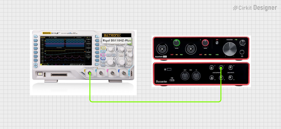
This circuit consists of an audio interface device, the Scarlett 4i4, connected to an oscilloscope. The purpose of this setup is to route an audio signal from the Scarlett 4i4 to the oscilloscope for signal analysis. The audio interface outputs the signal through its Line Out 1, which is then captured by Channel 1 (Ch1) of the oscilloscope. This configuration allows for the visualization and examination of the audio waveform output from the Scarlett 4i4.
Component List
Oscilloscope
- Description: A device used to display and analyze the waveform of electronic signals.
- Pins:
- Ch2
- Ch3
- Ch4
- Ch1
Scarlett 4i4
- Description: An audio interface device that allows for multiple audio inputs and outputs.
- Pins:
- Line In 1
- Line In 2
- Line In 3
- Line In 4
- Line Out 1
- Line Out 2
- Line Out 3
- Line Out 4
Wiring Details
Scarlett 4i4
- Line Out 1: Connected to the Ch1 of the Oscilloscope.
Oscilloscope
- Ch1: Connected to the Line Out 1 of the Scarlett 4i4.
Documented Code
There is no embedded code provided for any microcontrollers in this circuit. Therefore, this section is not applicable to the current documentation.