
Arduino UNO and ESP8266 Wi-Fi Controlled Battery-Powered Robot Car
View and Edit Project In Cirkit Designer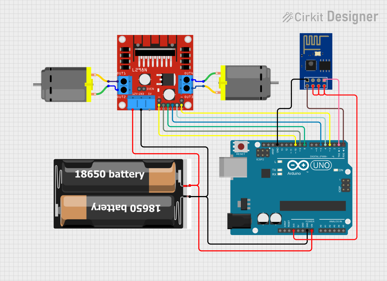
Circuit Documentation
Summary
This circuit is designed to control a robot using an Arduino UNO and an ESP8266 ESP-01 WiFi module. The Arduino UNO receives commands from the ESP8266 via UART and controls the H-bridge to drive two DC motors. The ESP8266 sets up a web server to allow remote control of the robot via a web interface.
Component List
Arduino UNO
- Description: A microcontroller board based on the ATmega328P.
- Pins: UNUSED, IOREF, Reset, 3.3V, 5V, GND, Vin, A0, A1, A2, A3, A4, A5, SCL, SDA, AREF, D13, D12, D11, D10, D9, D8, D7, D6, D5, D4, D3, D2, D1, D0
Puente H carrito
- Description: An H-bridge motor driver for controlling DC motors.
- Pins: OUT1, OUT2, OUT3, OUT4, 12V, GND, 5V, ENA, IN1, IN2, IN3, IN4, ENB, 5VEN
DC Motor
- Description: A standard DC motor.
- Pins: pin 1, pin 2
2x 18650
- Description: A battery pack consisting of two 18650 batteries.
- Pins: vcc, gnd
ESP8266 ESP-01 WiFi Module
- Description: A WiFi module based on the ESP8266 chip.
- Pins: TXD, CH_PD, RST, VCC, GND, GPIO_2, GPIO_0, RXD
Wiring Details
Arduino UNO
3.3V connected to:
- ESP8266 ESP-01 WiFi Module: CH_PD, RST, VCC
GND connected to:
- 2x 18650: gnd
- Puente H carrito: GND
- ESP8266 ESP-01 WiFi Module: GND
Vin connected to:
- 2x 18650: vcc
- Puente H carrito: 12V
D10 connected to:
- Puente H carrito: ENA
D9 connected to:
- Puente H carrito: IN1
D8 connected to:
- Puente H carrito: IN2
D5 connected to:
- Puente H carrito: IN3
D4 connected to:
- Puente H carrito: IN4
D3 connected to:
- Puente H carrito: ENB
D1 connected to:
- ESP8266 ESP-01 WiFi Module: RXD
D0 connected to:
- ESP8266 ESP-01 WiFi Module: TXD
Puente H carrito
OUT1 connected to:
- DC Motor: pin 2
OUT2 connected to:
- DC Motor: pin 1
OUT3 connected to:
- DC Motor: pin 2
OUT4 connected to:
- DC Motor: pin 1
DC Motor
Motor 1
- pin 1 connected to: Puente H carrito: OUT2
- pin 2 connected to: Puente H carrito: OUT1
Motor 2
- pin 1 connected to: Puente H carrito: OUT4
- pin 2 connected to: Puente H carrito: OUT3
2x 18650
vcc connected to:
- Arduino UNO: Vin
- Puente H carrito: 12V
gnd connected to:
- Arduino UNO: GND
- Puente H carrito: GND
ESP8266 ESP-01 WiFi Module
- CH_PD connected to: Arduino UNO: 3.3V
- RST connected to: Arduino UNO: 3.3V
- VCC connected to: Arduino UNO: 3.3V
- GND connected to: Arduino UNO: GND
- RXD connected to: Arduino UNO: D1
- TXD connected to: Arduino UNO: D0
Code Documentation
Arduino UNO Code
// Arduino UNO code
/*
 * This Arduino Sketch receives commands from the ESP8266 ESP-01 module via
 * UART and controls the H-bridge and motors accordingly.
 */

// Pin definitions
const int trigPin = 6;
const int echoPin = 7;
const int motorA1 = 9;
const int motorA2 = 8;
const int motorB1 = 5;
const int motorB2 = 4;
const int enableA = 10;
const int enableB = 3;

void setup() {
  // Initialize serial communication
  Serial.begin(9600);

  // Initialize pins
  pinMode(trigPin, OUTPUT);
  pinMode(echoPin, INPUT);
  pinMode(motorA1, OUTPUT);
  pinMode(motorA2, OUTPUT);
  pinMode(motorB1, OUTPUT);
  pinMode(motorB2, OUTPUT);
  pinMode(enableA, OUTPUT);
  pinMode(enableB, OUTPUT);

  // Enable motors
  analogWrite(enableA, 255);
  analogWrite(enableB, 255);
}

void loop() {
  if (Serial.available() > 0) {
    String command = Serial.readStringUntil('\n');
    command.trim();
    if (command == "forward") {
      moveForward();
    } else if (command == "backward") {
      moveBackward();
    } else if (command == "left") {
      turnLeft();
    } else if (command == "right") {
      turnRight();
    } else if (command == "stop") {
      stopMotors();
    }
  }
}

// Motor control functions
void moveForward() {
  digitalWrite(motorA1, HIGH);
  digitalWrite(motorA2, LOW);
  digitalWrite(motorB1, HIGH);
  digitalWrite(motorB2, LOW);
}

void moveBackward() {
  digitalWrite(motorA1, LOW);
  digitalWrite(motorA2, HIGH);
  digitalWrite(motorB1, LOW);
  digitalWrite(motorB2, HIGH);
}

void turnRight() {
  digitalWrite(motorA1, LOW);
  digitalWrite(motorA2, HIGH);
  digitalWrite(motorB1, HIGH);
  digitalWrite(motorB2, LOW);
}

void turnLeft() {
  digitalWrite(motorA1, HIGH);
  digitalWrite(motorA2, LOW);
  digitalWrite(motorB1, LOW);
  digitalWrite(motorB2, HIGH);
}

void stopMotors() {
  digitalWrite(motorA1, LOW);
  digitalWrite(motorA2, LOW);
  digitalWrite(motorB1, LOW);
  digitalWrite(motorB2, LOW);
}
ESP8266 ESP-01 Code
/*
   This Arduino Sketch sets up a web server on the ESP8266 ESP-01 module to
   control the movement of a robot via the Arduino UNO. The web server has
   buttons to send commands to the Arduino to move forward, backward, left,
   right, and stop.
*/

#include <ESP8266WiFi.h>

// WiFi credentials
const char* ssid = "your_SSID";
const char* password = "your_PASSWORD";

WiFiServer server(80);

void setup() {
  // Initialize serial communication
  Serial.begin(9600);
  delay(10);

  // Connect to WiFi
  WiFi.begin(ssid, password);
  while (WiFi.status() != WL_CONNECTED) {
    delay(500);
    Serial.print(".");
  }
  Serial.println("");
  Serial.print("Connected to ");
  Serial.println(ssid);
  Serial.print("IP address: ");
  Serial.println(WiFi.localIP());
  // Start the server
  server.begin();
  Serial.println("Server started");
}

void loop() {
  WiFiClient client = server.available(); // Listen on port 80
  if (client) {
    Serial.println("New connection");
    String request = client.readStringUntil('\r'); // Read HTTP request
    Serial.println(request);
    client.flush();

    // Handle buttons
    if (request.indexOf("/forward") != -1) {
      Serial.println("Command: forward"); // Send forward command
      Serial.write("forward\n");
    }
    if (request.indexOf("/backward") != -1) {
      Serial.println("Command: backward"); // Send backward command
      Serial.write("backward\n");
    }
    if (request.indexOf("/left") != -1) {
      Serial.println("Command: left"); // Send left command
      Serial.write("left\n");
    }
    if (request.indexOf("/right") != -1) {
      Serial.println("Command: right"); // Send right command
      Serial.write("right\n");
    }
    if (request.indexOf