Arduino-Based Gas Detection and Alert System with GSM Notification
Circuit Documentation
Summary
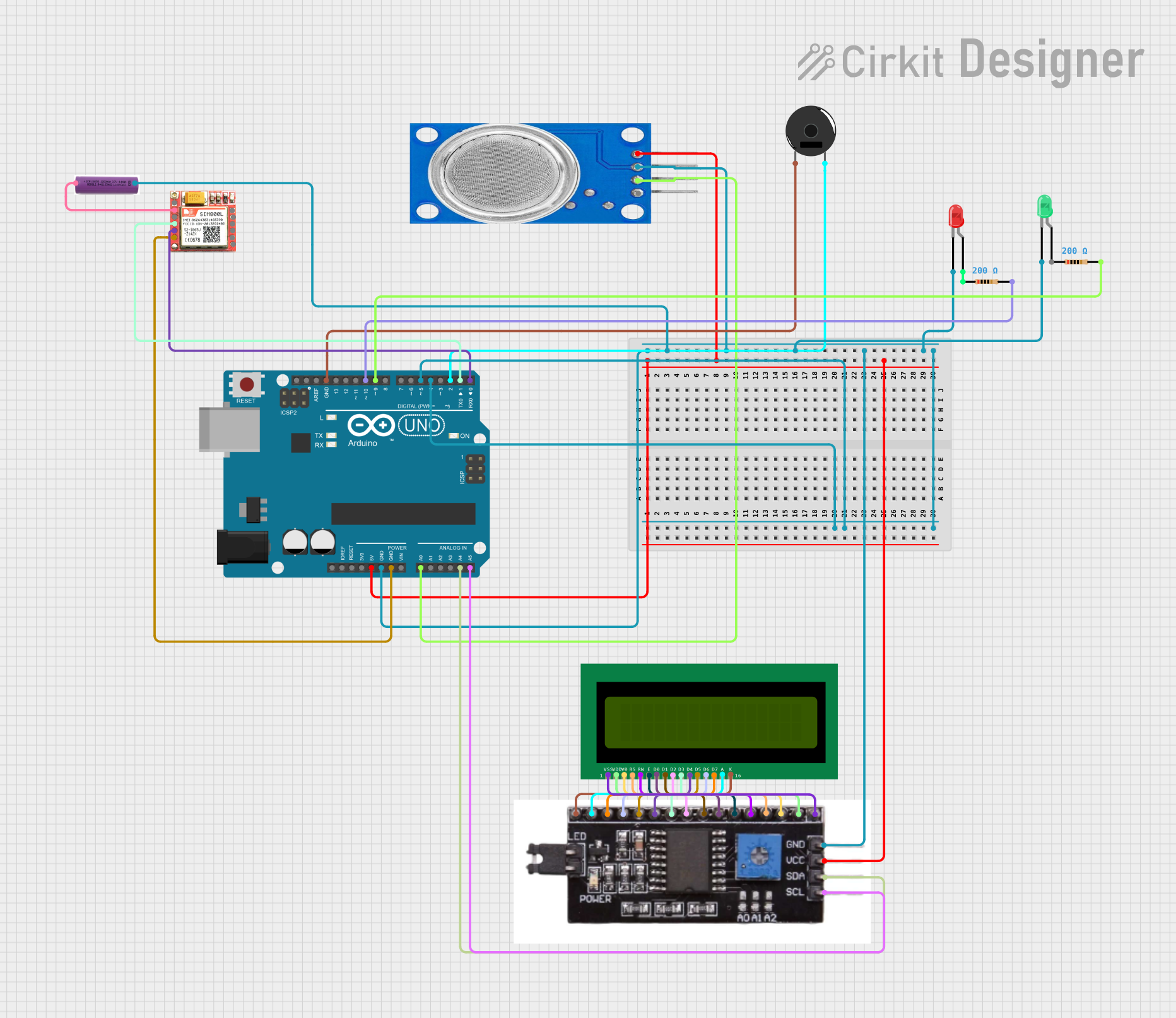
The circuit in question is designed to monitor air quality using an MQ135 gas sensor and to alert the user in case of gas detection. The system uses an Arduino UNO as the central processing unit, which controls the various peripherals including LEDs, an LCD display, a buzzer, and a SIM800L GSM module for communication. The circuit is powered by a 3.7V battery. The Arduino UNO reads the air quality index from the MQ135 sensor and displays the value on an LCD. If the gas concentration exceeds a predefined threshold, the system activates a red LED and a buzzer as immediate alerts and sends an SMS and makes a call using the SIM800L module for remote notification.
Component List
LEDs
- Red LED: A two-pin LED that lights up red when activated.
- Green LED: A two-pin LED that lights up green when activated.
Sensors and Modules
- MQ135 Gas Sensor: An analog gas sensor for detecting a wide range of gases, including NH3, NOx, alcohol, benzene, smoke, and CO2.
- SIM800L GSM Module: A module that allows the microcontroller to communicate over a GSM network. It can send SMS messages and make calls.
- 16X2 LCD: A liquid crystal display that can show 16 characters per line on 2 lines.
- I2C Module: An interface module that allows the LCD to communicate with the Arduino over the I2C protocol.
Power Supply
- 3.7V Battery: Provides power to the circuit.
Passive Components
- Resistors: Two resistors, each with a resistance of 200 Ohms, used for current limiting for the LEDs.
Actuators
- Piezo Buzzer: An electronic device that produces sound when an electrical signal is applied.
Microcontroller
- Arduino UNO: A microcontroller board based on the ATmega328P, with a variety of digital and analog I/O pins.
Wiring Details
LEDs
- Red LED: Anode connected to a 200 Ohm resistor, which is then connected to pin D10 of the Arduino. Cathode connected to GND.
- Green LED: Anode connected directly to pin D5 of the Arduino. Cathode connected to GND.
Sensors and Modules
- MQ135 Gas Sensor: VCC connected to 5V on the Arduino, GND to GND, and A0 to analog pin A0 on the Arduino.
- SIM800L GSM Module: VCC connected to the positive terminal of the 3.7V battery, GND to GND, RXD to pin D1 on the Arduino, and TXD to pin D0 on the Arduino.
- 16X2 LCD: Connected via the I2C Module, which interfaces with the Arduino's A4 (SDA) and A5 (SCL) pins.
- I2C Module: VCC connected to 5V on the Arduino, GND to GND, SDA to A4, and SCL to A5.
Power Supply
- 3.7V Battery: Positive terminal connected to VCC on the SIM800L GSM Module, negative terminal connected to GND.
Actuators
- Piezo Buzzer: One pin connected to pin D2 on the Arduino, the other pin to GND.
Documented Code
#include <Wire.h>
#include <LiquidCrystal_I2C.h>
#include <SoftwareSerial.h>

#define MQ135_PIN A0
#define RED_LED_PIN 4
#define GREEN_LED_PIN 5
#define BUZZER_PIN 2
#define GSM_RX_PIN 1
#define GSM_TX_PIN 0

LiquidCrystal_I2C lcd(0x27, 16, 2);
SoftwareSerial gsm(GSM_RX_PIN, GSM_TX_PIN);

const int threshold = 310;
const unsigned long smsInterval = 60000;
const unsigned long callInterval = 180000;
unsigned long lastSmsTime = 0;
unsigned long lastCallTime = 0;

// Timer variables for LED blinking and buzzer activation
unsigned long ledBlinkTimer = 0;
unsigned long buzzerTimer = 0;

void setup() {
  pinMode(RED_LED_PIN, OUTPUT);
  pinMode(GREEN_LED_PIN, OUTPUT);
  pinMode(BUZZER_PIN, OUTPUT);
  lcd.begin();
  lcd.backlight();
  gsm.begin(9600);
  digitalWrite(GREEN_LED_PIN, HIGH);
}

void loop() {
  int mq135Value = analogRead(MQ135_PIN);
  lcd.setCursor(0, 0);
  if (mq135Value > threshold) {
    lcd.print("Gas Detected");
    digitalWrite(GREEN_LED_PIN, LOW);
    startBlinkingRedLed();
    startBuzzer();
    sendAlert();
  } else {
    lcd.print("No Gas Detected");
    digitalWrite(GREEN_LED_PIN, HIGH);
    digitalWrite(RED_LED_PIN, LOW);
    noTone(BUZZER_PIN);
  }
  lcd.setCursor(0, 1);
  lcd.print("AQI: ");
  lcd.print(mq135Value);
  handleLedBlinking();
  handleBuzzer();
  delay(1000);
}

void startBlinkingRedLed() {
  ledBlinkTimer = millis();
}

void handleLedBlinking() {
  if (millis() - ledBlinkTimer >= 500) {
    digitalWrite(RED_LED_PIN, !digitalRead(RED_LED_PIN));
    ledBlinkTimer = millis();
  }
}

void startBuzzer() {
  buzzerTimer = millis();
  tone(BUZZER_PIN, 325);
}

void handleBuzzer() {
  if (millis() - buzzerTimer >= 5000) {
    noTone(BUZZER_PIN);
  }
}

void sendAlert() {
  sendSms();
  makeCall();
}

void sendSms() {
  unsigned long currentTime = millis();
  if (currentTime - lastSmsTime >= smsInterval) {
    gsm.print("AT+CMGF=1\r");
    delay(100);
    gsm.print("AT+CMGS=\"+918446656933\"\r");
    delay(100);
    gsm.print("Gas leakage detected");
    delay(100);
    gsm.write(26);
    lastSmsTime = currentTime;
  }
}

void makeCall() {
  unsigned long currentTime = millis();
  if (currentTime - lastCallTime >= callInterval) {
    gsm.print("ATD+918446656933;\r");
    delay(30000);
    gsm.print("ATH\r");
    lastCallTime = currentTime;
  }
}
This code is responsible for initializing the system, reading sensor data, and controlling the outputs based on the sensor readings. It also handles communication with the GSM module to send alerts when gas is detected.