
ESP32-Based Ultrasonic Liquid Level Indicator with I2C LCD Display
View and Edit Project In Cirkit Designer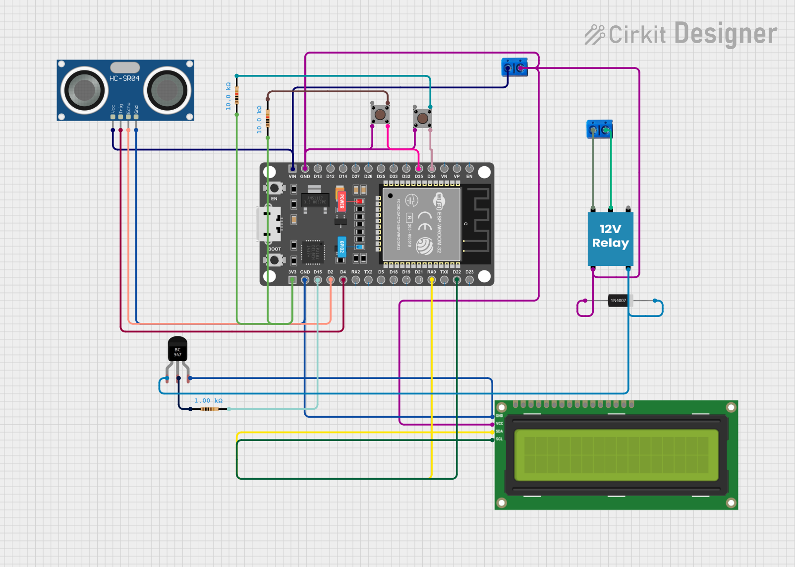
Circuit Documentation
Summary
This circuit is designed to monitor the level of a tank using an ultrasonic sensor (HC-SR04) and display the information on an I2C LCD screen. It includes user input through pushbuttons to set and calibrate the system. The ESP32 microcontroller is used to process the sensor data, control the LCD, and manage the system's state. A relay is included to control an external device based on the tank level, and a transistor is used to drive the relay. Protection diodes are in place to prevent reverse current flow. The circuit also features resistors for current limiting and pull-up/down configurations.
Component List
Microcontroller
- ESP 32 DEVKIT V1 (30 pins): A microcontroller with WiFi and Bluetooth capabilities, featuring a variety of digital and analog I/O pins.
Display
- I2C LCD 16x2 Screen: A liquid crystal display that can show 16 characters per line, with 2 lines. It uses the I2C communication protocol.
Sensor
- HC-SR04 Ultrasonic Sensor: An ultrasonic distance sensor that can measure distances by emitting ultrasonic waves and measuring the time taken for the echo to return.
Transistor
- BC547 Transistor: A general-purpose NPN bipolar junction transistor used for switching and amplification.
Diode
- 1N4007 Rectifier Diode: A general-purpose silicon rectifier diode with a high reverse voltage capability.
Switches
- Pushbutton: A simple switch mechanism for control of a circuit.
Resistors
- Resistor (1k Ohms): A resistor with a resistance of 1,000 Ohms.
- Resistor (10k Ohms): A resistor with a resistance of 10,000 Ohms.
Relay
- 12V Relay: An electromechanical switch that allows a low-power circuit to switch a relatively high current/voltage load.
Connectors
- Terminal PCB 2 Pin: A two-pin terminal block for connecting external wires to the PCB.
Wiring Details
ESP 32 DEVKIT V1 (30 pins)
EN,VP,VN,D25,D26,D27,D14,D12,D13,VIN,3V3,D15,D2,D4,RX2,TX2,D5,D18,D19,D21,RX0,TX0,D22,D23: Various I/O pins used for interfacing with other components.GND: Connected to the ground plane of the circuit.
I2C LCD 16x2 Screen
SCL: Connected to theD22pin of the ESP32 for I2C clock signal.SDA: Connected to theRX0pin of the ESP32 for I2C data signal.VCC (5V): Connected to the positive voltage supply.GND: Connected to the ground plane of the circuit.
HC-SR04 Ultrasonic Sensor
VCC: Connected to theVINpin of the ESP32 for power supply.TRIG: Connected to theD4pin of the ESP32 to trigger ultrasonic pulses.ECHO: Connected to theD2pin of the ESP32 to receive the echo signal.GND: Connected to the ground plane of the circuit.
BC547 Transistor
Collector: Connected to theNOpin of the relay and theCathodeof the diode.Base: Connected to thepin2of a 1k Ohm resistor.Emitter: Connected to the ground plane of the circuit.
1N4007 Rectifier Diode
Cathode: Connected to theCollectorof the BC547 transistor.Anode: Connected to theNCpin of the relay.
Pushbutton
Pin 4 (out): Connected to theD34andD35pins of the ESP32 for user input.Pin 2 (in): Connected to theNCpin of the relay and the ground plane of the circuit.Pin 3 (out): Connected to thepin2of 10k Ohm resistors.
Resistor (1k Ohms)
pin1: Connected to theBaseof the BC547 transistor.pin2: Connected to theD15pin of the ESP32.
Resistor (10k Ohms)
pin1: Connected to the3V3pin of the ESP32 and other 10k Ohm resistors.pin2: Connected to thePin 3 (out)of the pushbuttons.
12V Relay
+: Connected to the positive terminal of an external 12V power supply.-: Connected to the ground plane of the circuit.C: Connected to an external load or device.NC: Connected to thePin 2 (in)of the pushbuttons and theAnodeof the diode.NO: Connected to theCollectorof the BC547 transistor.
Terminal PCB 2 Pin
Pin A: Connected to theVCCof the HC-SR04 sensor and the+pin of the relay.Pin B: Connected to theGNDof the HC-SR04 sensor and theCpin of the relay.
Documented Code
#include <Wire.h>
#include <LiquidCrystal_I2C.h>
#include "EEPROM.h"
// Set the LCD address to 0x27 for a 16 chars and 2 line display
LiquidCrystal_I2C lcd(0x27, 16, 2);
long duration, inches;
int lvl,m,sm,fulllvl,lowlvl,lowset,mode,dly,inch;
bool st,out;
void setup()
{
    pinMode(2, INPUT);
    pinMode(4, OUTPUT);
    pinMode(15, OUTPUT);
    pinMode(34, INPUT);
    pinMode(35, INPUT);
   Serial.begin(9600);
  EEPROM.begin(4);
   //-----------
	// initialize the LCD
	lcd.begin();

	// Turn on the blacklight and print a message.
	lcd.backlight();
	lcd.print("TANK LEVEL: 100%");
  lcd.setCursor(0, 1);
  lcd.print("MODE:A   OUT:OFF");
    mode=EEPROM.read(0);
    lowset=EEPROM.read(1);
    fulllvl=EEPROM.read(2);
    lowlvl=EEPROM.read(3);
    if(mode>1)mode=0;
    if(lowset<10)lowset=10;
    if(lowset>90)lowset=10;
    if(fulllvl>100)lowlvl=0;
    if(lowlvl>120)lowlvl=1;


}

void loop()
{
  dly++;
	digitalWrite(4, LOW);
   delayMicroseconds(2);
   digitalWrite(4, HIGH);
   delayMicroseconds(10);
   digitalWrite(4, LOW);
   duration = pulseIn(2, HIGH);
   inches = microsecondsToInches(duration);
 inch=inches-fulllvl;
   lvl=(((lowlvl-inch))*100)/(lowlvl);
   if(lvl<0)lvl=0;
if(lvl>100)lvl=100;
//----------------------------------
if( digitalRead(35)&digitalRead(34))st=0;
   if( !digitalRead(34)&!st){
     st=1;
    if(m==0){m=1;
lcd.clear();
    lcd.setCursor(0, 0);
lcd.print("      MODE      ");}
else if(m==2|m==1){
  lcd.setCursor(0, 1);
  lcd.print("               ");
  if(sm==0){sm=1;

  }
else  if(sm==1){sm=0;
  if(m==1) EEPROM.write(0, mode);
 else EEPROM.write(1, lowset);
EEPROM.commit();


  }


}
     else if(m==3){
fulllvl=inches;
 lcd.setCursor(7, 1);
  lcd.print(fulllvl);
EEPROM.write(2, fulllvl);
EEPROM.commit();
delay(1000);
lcd.setCursor(0, 1);
  lcd.print("               ");
    }

    else if(m==4){
lowlvl=inch;
if(lowlvl<1)lowlvl=1;
 lcd.setCursor(7, 1);
  lcd.print(lowlvl);
EEPROM.write(3, lowlvl);
EEPROM.commit();
delay(1000);
lcd.setCursor(0, 1);
  lcd.print("               ");
    }
    else if(m==5){
      m=0;

lcd.setCursor(0, 0);
	lcd.print("TANK LEVEL: 100%");
  lcd.setCursor(0, 1);
  lcd.print("MODE:A   OUT:OFF");
      }

   }
 if( !digitalRead(35)&!st){
   st=1;
if(m==0){
 if(mode