Cirkit Designer
Your all-in-one circuit design IDE
Home /
Project Documentation
Arduino-Based Anti-Electric Shock Device with ACS712 Current Sensors and Relay Control
Circuit Documentation
Summary
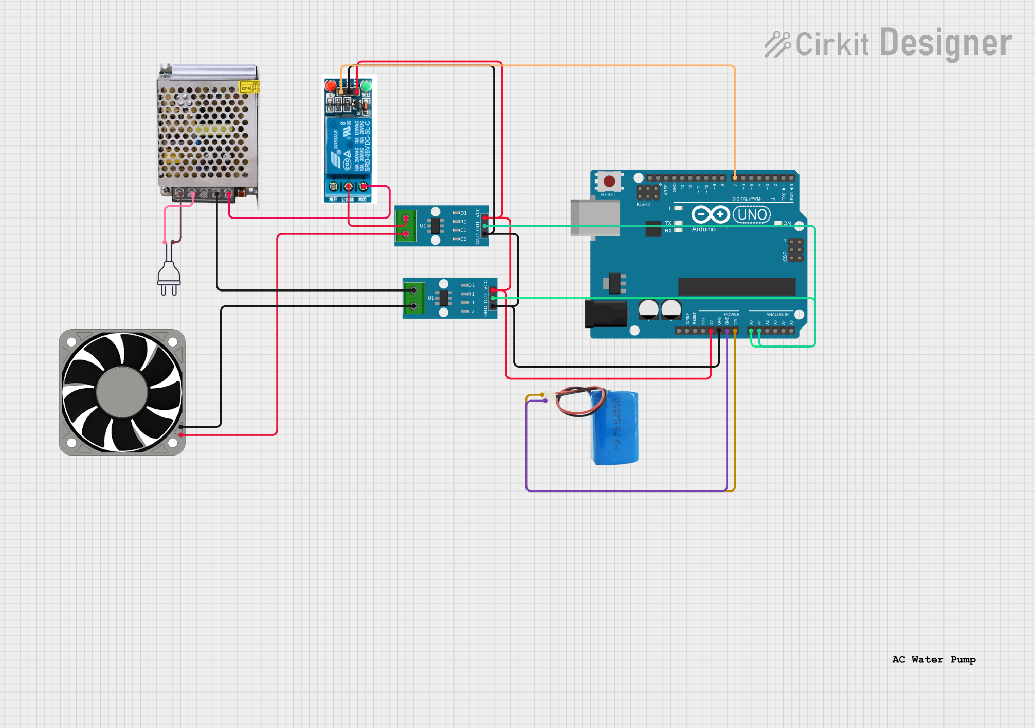
This document provides a detailed overview of a circuit designed to monitor and control electrical currents using ACS712 current sensors, an Arduino UNO microcontroller, and a 5V relay. The circuit includes a power supply, a 12V fan, and a 5V battery. The Arduino UNO reads current values from the sensors and controls the relay based on predefined thresholds to prevent electric shock.
Component List
ACS712 Current Sensor 5A 20A 30A
- Description: Current sensor module capable of measuring up to 30A.
- Pins: 1, 2, GND, OUT, VCC
Arduino UNO
- Description: Microcontroller board based on the ATmega328P.
- Pins: UNUSED, IOREF, Reset, 3.3V, 5V, GND, Vin, A0, A1, A2, A3, A4, A5, SCL, SDA, AREF, D13, D12, D11, D10, D9, D8, D7, D6, D5, D4, D3, D2, D1, D0
5V Battery
- Description: Power source providing 5V.
- Pins: positive, negative
POWER SUPPLY 5V 5AMP
- Description: Power supply unit providing 5V at 5A.
- Pins: 220V Positive Pole (AC), 220V Negative Pole (AC), GND, GND (DC), 12V-24V Output (DC)
Power 220V
- Description: 220V AC power source.
- Pins: hot wire, neutral wire
40 Fan 12V
- Description: 12V fan for cooling purposes.
- Pins: +12V, -12V
5V Relay
- Description: Relay module for switching circuits.
- Pins: Normally Open, Common terminal, Normally Closed, In, GND, VCC
Wiring Details
ACS712 Current Sensor 5A 20A 30A (Instance 1)
- Pin 1: Connected to the Common terminal of the 5V relay.
- Pin 2: Connected to the +12V pin of the 12V fan.
- GND: Connected to the GND pin of the Arduino UNO, GND pin of the 5V relay, and GND pin of the second ACS712 sensor.
- OUT: Connected to the A1 pin of the Arduino UNO.
- VCC: Connected to the 5V pin of the Arduino UNO, VCC pin of the 5V relay, and VCC pin of the second ACS712 sensor.
ACS712 Current Sensor 5A 20A 30A (Instance 2)
- Pin 1: Connected to the GND (DC) pin of the POWER SUPPLY 5V 5AMP.
- Pin 2: Connected to the -12V pin of the 12V fan.
- GND: Connected to the GND pin of the Arduino UNO, GND pin of the 5V relay, and GND pin of the first ACS712 sensor.
- OUT: Connected to the A0 pin of the Arduino UNO.
- VCC: Connected to the 5V pin of the Arduino UNO, VCC pin of the 5V relay, and VCC pin of the first ACS712 sensor.
Arduino UNO
- GND: Connected to the GND pin of the first ACS712 sensor, GND pin of the 5V relay, GND pin of the second ACS712 sensor, and negative pin of the 5V battery.
- A1: Connected to the OUT pin of the first ACS712 sensor.
- 5V: Connected to the VCC pin of the first ACS712 sensor, VCC pin of the 5V relay, and VCC pin of the second ACS712 sensor.
- A0: Connected to the OUT pin of the second ACS712 sensor.
- Vin: Connected to the positive pin of the 5V battery.
- D7: Connected to the In pin of the 5V relay.
5V Battery
- negative: Connected to the GND pin of the Arduino UNO.
- positive: Connected to the Vin pin of the Arduino UNO.
POWER SUPPLY 5V 5AMP
- 220V Positive Pole (AC): Connected to the hot wire of the 220V power source.
- 220V Negative Pole (AC): Connected to the neutral wire of the 220V power source.
- GND (DC): Connected to the Pin 1 of the second ACS712 sensor.
- 12V-24V Output (DC): Connected to the Normally Closed pin of the 5V relay.
Power 220V
- hot wire: Connected to the 220V Positive Pole (AC) pin of the POWER SUPPLY 5V 5AMP.
- neutral wire: Connected to the 220V Negative Pole (AC) pin of the POWER SUPPLY 5V 5AMP.
40 Fan 12V
- +12V: Connected to the Pin 2 of the first ACS712 sensor.
- -12V: Connected to the Pin 2 of the second ACS712 sensor.
5V Relay
- Normally Open: Not connected.
- Common terminal: Connected to the Pin 1 of the first ACS712 sensor.
- Normally Closed: Connected to the 12V-24V Output (DC) pin of the POWER SUPPLY 5V 5AMP.
- In: Connected to the D7 pin of the Arduino UNO.
- GND: Connected to the GND pin of the Arduino UNO, GND pin of the first ACS712 sensor, and GND pin of the second ACS712 sensor.
- VCC: Connected to the 5V pin of the Arduino UNO, VCC pin of the first ACS712 sensor, and VCC pin of the second ACS712 sensor.
Documented Code
#include <Relay.h> // Include relay library (if needed)

const int phaseCurrentPin = A0;  // Pin for phase current sensor (ACS712)
const int neutralCurrentPin = A1;  // Pin for neutral current sensor (ACS712)
const int relayPin = 7;  // Pin to control the relay (connected to relay module)

float phaseCurrent = 0;
float neutralCurrent = 0;
float phaseThreshold = 1.5;  // Threshold for phase current (in amps)
float neutralThreshold = 1.5;  // Threshold for neutral current (in amps)

// Calibration values for the ACS712 sensors (assuming 5V reference)
float offset = 2.5; // Middle value for ACS712 at no current, depends on your sensor
float sensitivity = 0.185;  // For ACS712 5A model, the sensitivity is 0.185V per Amp (check datasheet)

void setup() {
  Serial.begin(9600);
  pinMode(relayPin, OUTPUT);
  digitalWrite(relayPin, HIGH);  // Start with relay off (active low relay)

  // Print initial message
  Serial.println("Anti-Electric Shock Device initialized");
}

void loop() {
  // Read analog values from both current sensors
  int phaseReading = analogRead(phaseCurrentPin);
  int neutralReading = analogRead(neutralCurrentPin);

  // Convert sensor readings to voltage (assuming 5V ADC and 10-bit resolution)
  float phaseVoltage = (phaseReading * 5.0) / 1024.0;
  float neutralVoltage = (neutralReading * 5.0) / 1024.0;

  // Calculate the current from the sensor voltage
  phaseCurrent = (phaseVoltage - offset) / sensitivity;
  neutralCurrent = (neutralVoltage - offset) / sensitivity;

  // Output the measured currents to the serial monitor
  Serial.print("Phase Current: ");
  Serial.print(phaseCurrent);
  Serial.print(" A, ");
}
This code initializes the Arduino UNO to read current values from two ACS712 sensors and control a relay based on predefined current thresholds. The relay is used to prevent electric shock by disconnecting the circuit when the current exceeds the threshold.