
Circuit Documentation
Summary of the Circuit
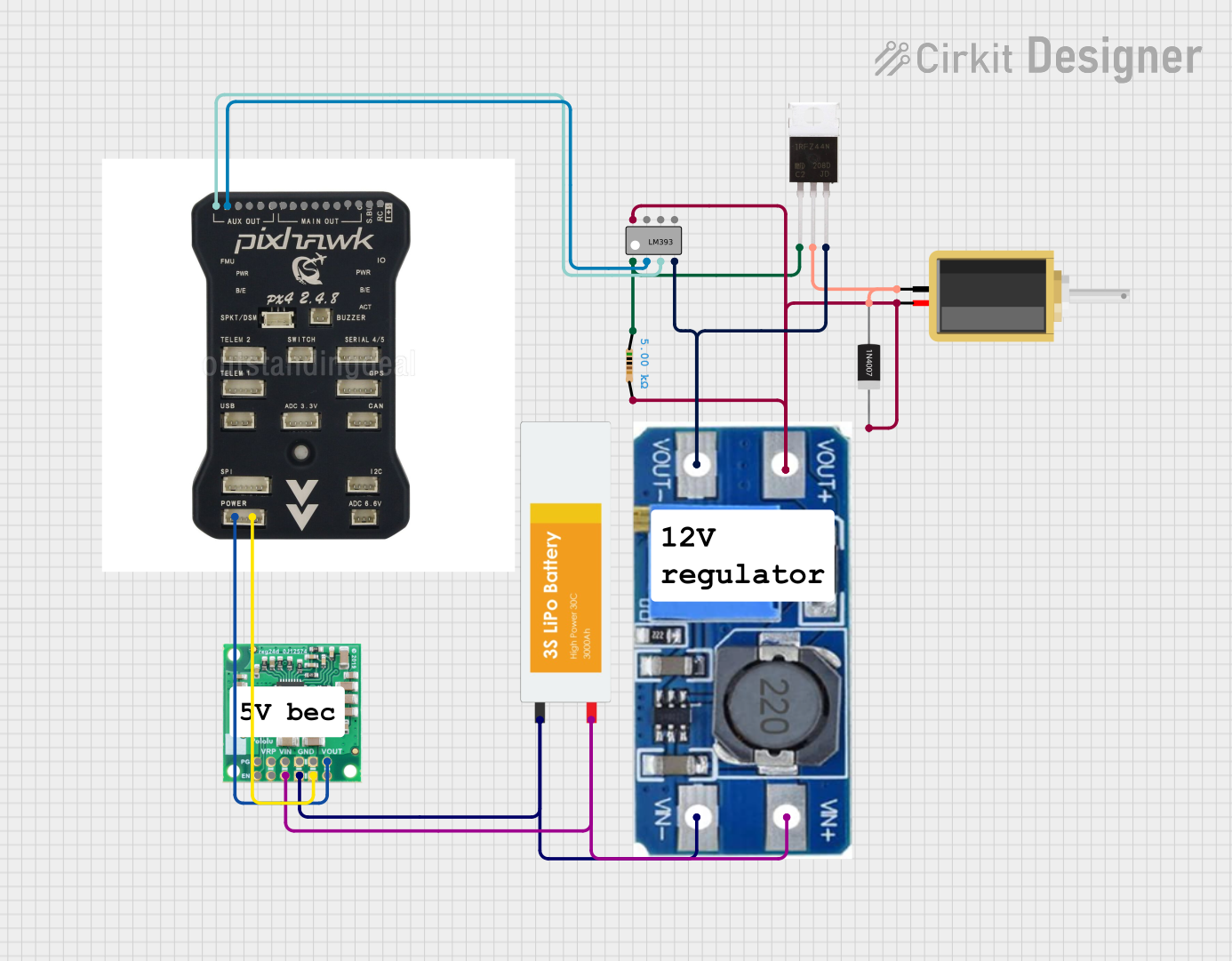
This circuit appears to be a control system that utilizes a comparator (LM393), a MOSFET (IRFZ44N), a microcontroller (pixhawk 2.4.8), power regulation components (Step Up Boost Power Converter, Adjustable Voltage Regulator, and 5V, 5.5A Step-Down Voltage Regulator D36V50F5), and a power source (Lipo Battery). The circuit is designed to drive a solenoid based on a signal processed by the LM393 comparator, which compares two inputs from the pixhawk microcontroller. The output of the comparator controls the gate of the MOSFET, which in turn controls the solenoid. Power regulation is achieved through the step-up and step-down voltage regulators, ensuring that components receive the correct operating voltages. A diode (1N4007) is used for protection against reverse current, and a resistor is included to limit the current to the gate of the MOSFET.
Component List
LM393 - Dual Differential Comparator
- Pins: Output A, Inverting Input A, Non-Inverting Input A, GND, VCC, Output B, Inverting Input B, Non-Inverting Input B
IRFZ44N - N-Channel MOSFET
- Pins: Gate, Drain, Source
Lipo Battery
- Pins: VCC, GND
Step Up Boost Power Converter, Adjustable Voltage Regulator
- Pins: VOUT+, VOUT-, VIN+, VIN-
pixhawk 2.4.8 - Microcontroller
- Pins: 1, 2, 3, 4, 5, 6, 8, rc, S.bus, 7, +5V, gnd
5V, 5.5A Step-Down Voltage Regulator D36V50F5
- Pins: PG, EN, VRP, VIN, GND, VOUT
Resistor
- Pins: pin1, pin2
- Properties: Resistance - 5000 Ohms
Solenoid
- Pins: pin1, pin2
1N4007 Rectifier Diode
- Pins: Cathode, Anode
Wiring Details
LM393 - Dual Differential Comparator
- Output A connected to Gate of IRFZ44N and pin1 of Resistor
- Inverting Input A connected to pin 2 of pixhawk 2.4.8
- Non-Inverting Input A connected to pin 1 of pixhawk 2.4.8
- GND connected to Source of IRFZ44N and VOUT- of Step Up Boost Power Converter
- VCC connected to Cathode of 1N4007 Diode, VOUT+ of Step Up Boost Power Converter, pin2 of Solenoid, and pin2 of Resistor
IRFZ44N - N-Channel MOSFET
- Gate connected to Output A of LM393 and pin1 of Resistor
- Drain connected to Anode of 1N4007 Diode and pin1 of Solenoid
- Source connected to GND of LM393 and VOUT- of Step Up Boost Power Converter
Lipo Battery
- VCC connected to VIN+ of Step Up Boost Power Converter and VIN of 5V, 5.5A Step-Down Voltage Regulator
- GND connected to VIN- of Step Up Boost Power Converter and GND of 5V, 5.5A Step-Down Voltage Regulator
Step Up Boost Power Converter, Adjustable Voltage Regulator
- VOUT+ connected to VCC of LM393, Cathode of 1N4007 Diode, pin2 of Solenoid, and pin2 of Resistor
- VOUT- connected to GND of LM393 and Source of IRFZ44N
- VIN+ connected to VCC of Lipo Battery
- VIN- connected to GND of Lipo Battery
pixhawk 2.4.8 - Microcontroller
- Pin 1 connected to Non-Inverting Input A of LM393
- Pin 2 connected to Inverting Input A of LM393
- +5V connected to VOUT of 5V, 5.5A Step-Down Voltage Regulator
- gnd connected to GND of 5V, 5.5A Step-Down Voltage Regulator
5V, 5.5A Step-Down Voltage Regulator D36V50F5
- VIN connected to VCC of Lipo Battery
- GND connected to GND of Lipo Battery and gnd of pixhawk 2.4.8
- VOUT connected to +5V of pixhawk 2.4.8
Resistor
- pin1 connected to Output A of LM393 and Gate of IRFZ44N
- pin2 connected to VCC of LM393
Solenoid
- pin1 connected to Drain of IRFZ44N
- pin2 connected to VCC of LM393
1N4007 Rectifier Diode
- Cathode connected to VCC of LM393
- Anode connected to Drain of IRFZ44N
Documented Code
There is no code provided for the microcontroller in this circuit. If code is later provided, it should be documented here with explanations of how it interacts with the hardware components and the intended logic flow.