
Arduino UNO Controlled Brushless Motor System with GPS and IMU
View and Edit Project In Cirkit Designer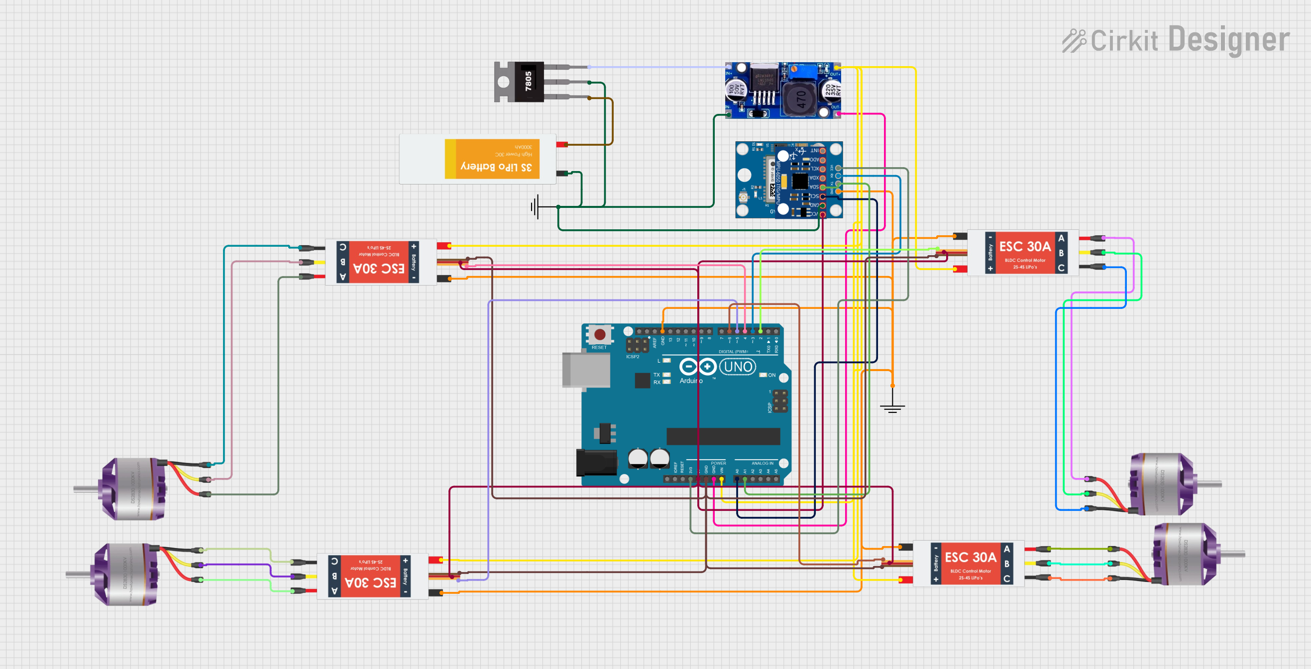
Circuit Documentation
Summary
This document provides a detailed overview of a circuit designed to control multiple brushless motors using Electronic Speed Controllers (ESCs) and an Arduino UNO. The circuit also includes a GPS module, an MPU-6050 sensor, and a power management system using an LM2596 and a 7805 voltage regulator. The Arduino UNO serves as the central microcontroller, interfacing with the ESCs, sensors, and power modules to control the motors and gather data.
Component List
Brushless Motor
- Pins: L1, L2, L3
- Description: A motor that operates without brushes, typically used for high-efficiency and high-performance applications.
- Purpose: Drives the mechanical components of the system.
Electronic Speed Controller (ESC)
- Pins: Battery VCC, Battery GND, Signal, 5v out, GND out, M1, M2, M3
- Description: A device that controls the speed of the brushless motor by varying the power supplied to it.
- Purpose: Regulates the speed and direction of the brushless motors.
Arduino UNO
- Pins: UNUSED, IOREF, Reset, 3.3V, 5V, GND, Vin, A0, A1, A2, A3, A4, A5, SCL, SDA, AREF, D13, D12, D11, D10, D9, D8, D7, D6, D5, D4, D3, D2, D1, D0
- Description: A microcontroller board based on the ATmega328P.
- Purpose: Acts as the central control unit for the circuit.
GND
- Pins: GND
- Description: Ground connection.
- Purpose: Provides a common ground reference for the circuit.
Neo 6M GPS Module
- Pins: GND, TX, RX, VCC
- Description: A GPS module used for location tracking.
- Purpose: Provides GPS data to the Arduino UNO.
LM2596
- Pins: IN, OUT
- Description: A step-down voltage regulator.
- Purpose: Regulates the input voltage to a lower, stable output voltage.
MPU-6050
- Pins: VCC, GND, SCL, SDA, XDA, XCL, AD0, INT
- Description: A 6-axis motion tracking device.
- Purpose: Provides accelerometer and gyroscope data to the Arduino UNO.
7805
- Pins: Vin, Gnd, Vout
- Description: A voltage regulator that outputs a stable 5V.
- Purpose: Provides a stable 5V supply to the circuit.
Lipo Battery
- Pins: VCC, GND
- Description: A rechargeable lithium polymer battery.
- Purpose: Supplies power to the circuit.
Wiring Details
Brushless Motor
- L1 connected to M1 of the corresponding ESC.
- L2 connected to M2 of the corresponding ESC.
- L3 connected to M3 of the corresponding ESC.
Electronic Speed Controller (ESC)
- Battery VCC connected to Vin of the Arduino UNO and OUT of the LM2596.
- Battery GND connected to GND of the Arduino UNO and OUT of the LM2596.
- Signal connected to D2, D4, D5, D6 of the Arduino UNO.
- 5v out connected to 5V of the Arduino UNO and VCC of the MPU-6050.
- GND out connected to GND of the Arduino UNO and GND of the MPU-6050.
- M1 connected to L1 of the corresponding Brushless Motor.
- M2 connected to L2 of the corresponding Brushless Motor.
- M3 connected to L3 of the corresponding Brushless Motor.
Arduino UNO
- 3.3V connected to VCC of the Neo 6M GPS Module.
- 5V connected to 5v out of the ESCs and VCC of the MPU-6050.
- GND connected to GND out of the ESCs, OUT of the LM2596, and GND of the Neo 6M GPS Module.
- Vin connected to Battery VCC of the ESCs and OUT of the LM2596.
- A0 connected to SCL of the MPU-6050.
- A1 connected to SDA of the MPU-6050.
- D2 connected to Signal of one ESC.
- D3 connected to RX of the Neo 6M GPS Module.
- D4 connected to Signal of one ESC.
- D5 connected to Signal of one ESC.
- D6 connected to Signal of one ESC.
GND
- GND connected to IN of the LM2596, GND of the Lipo Battery, GND of the MPU-6050, and Gnd of the 7805.
Neo 6M GPS Module
- GND connected to GND of the Arduino UNO.
- TX not connected.
- RX connected to D3 of the Arduino UNO.
- VCC connected to 3.3V of the Arduino UNO.
LM2596
- IN connected to GND of the GND component.
- OUT connected to Vin and GND of the Arduino UNO and Battery VCC and Battery GND of the ESCs.
MPU-6050
- VCC connected to 5V of the Arduino UNO.
- GND connected to GND of the Arduino UNO.
- SCL connected to A0 of the Arduino UNO.
- SDA connected to A1 of the Arduino UNO.
7805
- Vin connected to VCC of the Lipo Battery.
- Gnd connected to GND of the GND component.
- Vout connected to IN of the LM2596.
Lipo Battery
- VCC connected to Vin of the 7805.
- GND connected to GND of the GND component.
Documented Code
Arduino UNO Code
void setup() {
  // put your setup code here, to run once:

}

void loop() {
  // put your main code here, to run repeatedly:

}
ESC Control Code
/*
 * This Arduino Sketch controls the ESCs connected to the Arduino UNO.
 * It drives the wheels by sending PWM signals to the ESCs.
 */

// Pin definitions
const int esc1Pin = 7;
const int esc2Pin = 6;
const int esc3Pin = 5;
const int esc4Pin = 4;

void setup() {
  // Initialize ESC pins as output
  pinMode(esc1Pin, OUTPUT);
  pinMode(esc2Pin, OUTPUT);
  pinMode(esc3Pin, OUTPUT);
  pinMode(esc4Pin, OUTPUT);

  // Initialize ESCs with a neutral signal (1500 microseconds)
  analogWrite(esc1Pin, 1500 / 4);
  analogWrite(esc2Pin, 1500 / 4);
  analogWrite(esc3Pin, 1500 / 4);
  analogWrite(esc4Pin, 1500 / 4);
}

void loop() {
  // Example: Drive all ESCs with a forward signal (1600 microseconds)
  analogWrite(esc1Pin, 1600 / 4);
  analogWrite(esc2Pin, 1600 / 4);
  analogWrite(esc3Pin, 1600 / 4);
  analogWrite(esc4Pin, 1600 / 4);

  delay(1000); // Wait for 1 second

  // Example: Stop all ESCs (1500 microseconds)
  analogWrite(esc1Pin, 1500 / 4);
  analogWrite(esc2Pin, 1500 / 4);
  analogWrite(esc3Pin, 1500 / 4);
  analogWrite(esc4Pin, 1500 / 4);

  delay(1000); // Wait for 1 second
}
This documentation provides a comprehensive overview of the circuit, including the components used, their wiring details, and the code running on the microcontrollers.