
ESP32-Controlled Security System with Ultrasonic Sensor, PIR Sensor, and Motorized Response
View and Edit Project In Cirkit Designer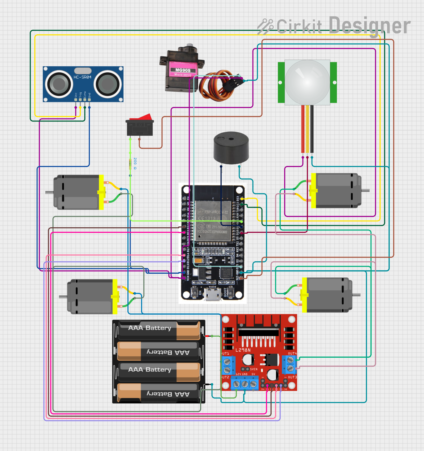
Circuit Documentation
Summary
This circuit integrates various sensors, actuators, and a microcontroller to form a complex system capable of sensing and actuation. The primary controller is an ESP32 microcontroller, which interfaces with an HC-SR04 Ultrasonic Sensor, a PIR sensor, a buzzer, an MG90S servo motor, and four DC motors through an L298N motor driver. The circuit is powered by a 4 x AAA battery mount, and a rocker switch is used to control the power supply to the ESP32. A resistor is also included in the circuit for current limiting purposes.
Component List
HC-SR04 Ultrasonic Sensor
- Pins: VCC, TRIG, ECHO, GND
- Description: This sensor is used for measuring distances using ultrasonic waves.
PIR Sensor
- Pins: VDD, SIG, GND
- Description: A motion sensor that detects the presence of humans or animals through changes in infrared levels.
Buzzer
- Pins: PIN, GND
- Description: An audible signaling device that can be used for alerts or alarms.
MG90S Servo Motor
- Pins: SIG, VCC, GND
- Description: A small servo motor for precise control of angular motion.
DC Motor
- Pins: pin 1, pin 2
- Description: An electric motor for converting electrical energy into mechanical rotation.
L298N DC Motor Driver
- Pins: OUT1, OUT2, 12V, GND, 5V, OUT3, OUT4, 5V-ENA-JMP-I, 5V-ENA-JMP-O, +5V-J1, +5V-J2, ENA, IN1, IN2, IN3, IN4, ENB
- Description: A module for controlling the direction and speed of DC motors.
ESP32
- Pins: EN, VP, VN, D34, D35, D32, D33, D25, D26, D27, D14, D12, D13, GND, VIN, 3V3, D15, D2, D4, RX2, TX2, D5, D18, D19, D21, RX0, TX0, D22, D23, BOOT
- Description: A powerful microcontroller with Wi-Fi and Bluetooth capabilities.
Rocker Switch
- Pins: 1, 2
- Description: A switch for turning the power supply on and off.
4 x AAA Battery Mount
- Pins: -, +
- Description: A battery holder for providing power to the circuit.
Resistor
- Pins: pin1, pin2
- Description: A passive two-terminal electrical component that implements electrical resistance as a circuit element.
- Properties: 200 Ohms resistance
Wiring Details
HC-SR04 Ultrasonic Sensor
- VCC connected to ESP32 VIN
- TRIG connected to ESP32 D23
- ECHO connected to ESP32 D22
- GND connected to ESP32 GND and Resistor pin2
PIR Sensor
- VDD connected to ESP32 VIN
- SIG connected to ESP32 D18
- GND connected to ESP32 GND
Buzzer
- PIN connected to ESP32 D19
- GND connected to ESP32 GND
MG90S Servo Motor
- SIG connected to ESP32 D15
- VCC connected to ESP32 VIN
- GND connected to ESP32 GND
DC Motors
- Motor 1 pin 1 connected to L298N OUT2
- Motor 1 pin 2 connected to L298N OUT1
- Motor 2 pin 1 connected to L298N OUT4
- Motor 2 pin 2 connected to L298N OUT3
- Motors 1 and 2 share the same connections on the L298N
L298N DC Motor Driver
- OUT1, OUT2, OUT3, OUT4 connected to corresponding DC Motor pins
- 12V connected to 4 x AAA Battery Mount +
- GND connected to ESP32 GND and 4 x AAA Battery Mount -
- IN1 connected to ESP32 D33
- IN2 connected to ESP32 D32
- IN3 connected to ESP32 D14
- IN4 connected to ESP32 D12
ESP32
- VIN connected to HC-SR04 VCC, PIR VDD, MG90S VCC
- GND connected to HC-SR04 GND, PIR GND, MG90S GND, Buzzer GND, L298N GND
- 3V3 connected to Rocker Switch pin 2
- D15, D19, D18, D23, D22, D33, D32, D14, D12 connected to corresponding components as detailed above
- D21 connected to Resistor pin1 and Rocker Switch pin 1
Rocker Switch
- Pin 1 connected to ESP32 D21 and Resistor pin1
- Pin 2 connected to ESP32 3V3
4 x AAA Battery Mount
-
- connected to L298N 12V
-
- connected to L298N GND
Resistor
- Pin1 connected to ESP32 D21 and Rocker Switch pin 1
- Pin2 connected to HC-SR04 GND
Documented Code
No code was provided for the microcontroller. The documentation of the code would typically include details on how the ESP32 is programmed to interact with the sensors, actuators, and motor driver, including initialization, main loop, interrupt service routines, and any relevant functions or libraries used.