
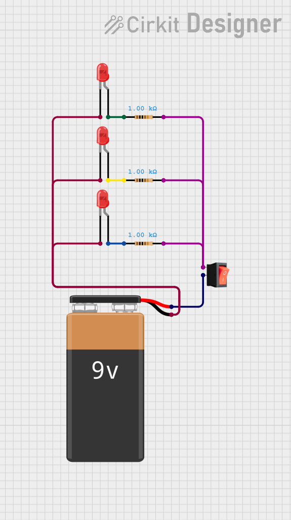
Circuit Documentation
Summary
This circuit consists of three red LEDs, three resistors, a 9V battery, and a rocker switch. The LEDs are connected in parallel, each with its own current-limiting resistor. The circuit is powered by a 9V battery, and the rocker switch is used to control the power to the LEDs.
Component List
LED: Two Pin (red)
- Pins: cathode, anode
- Description: A red light-emitting diode (LED) used to emit light when current flows through it.
9V Battery
- Pins: -, +
- Description: A 9V battery used as the power source for the circuit.
Resistor
- Pins: pin1, pin2
- Description: A resistor with a resistance of 1000 Ohms used to limit the current flowing through the LEDs.
- Properties:
- Resistance: 1000 Ohms
Rocker Switch
- Pins: output, input
- Description: A switch used to control the power to the circuit.
Wiring Details
LED: Two Pin (red)
LED 1
- Cathode: Connected to the negative terminal of the 9V battery.
- Anode: Connected to pin1 of Resistor 1.
LED 2
- Cathode: Connected to the negative terminal of the 9V battery.
- Anode: Connected to pin1 of Resistor 2.
LED 3
- Cathode: Connected to the negative terminal of the 9V battery.
- Anode: Connected to pin1 of Resistor 3.
9V Battery
- Negative terminal (-): Connected to the cathodes of all three LEDs.
- Positive terminal (+): Connected to the output pin of the rocker switch.
Resistor
Resistor 1
- Pin1: Connected to the anode of LED 1.
- Pin2: Connected to the input pin of the rocker switch.
Resistor 2
- Pin1: Connected to the anode of LED 2.
- Pin2: Connected to the input pin of the rocker switch.
Resistor 3
- Pin1: Connected to the anode of LED 3.
- Pin2: Connected to the input pin of the rocker switch.
Rocker Switch
- Output: Connected to the positive terminal of the 9V battery.
- Input: Connected to pin2 of Resistor 1, pin2 of Resistor 2, and pin2 of Resistor 3.
Code
There is no microcontroller code associated with this circuit.