
ESP32-Based Smart Interaction Device with RFID and Audio-Visual Feedback
View and Edit Project In Cirkit Designer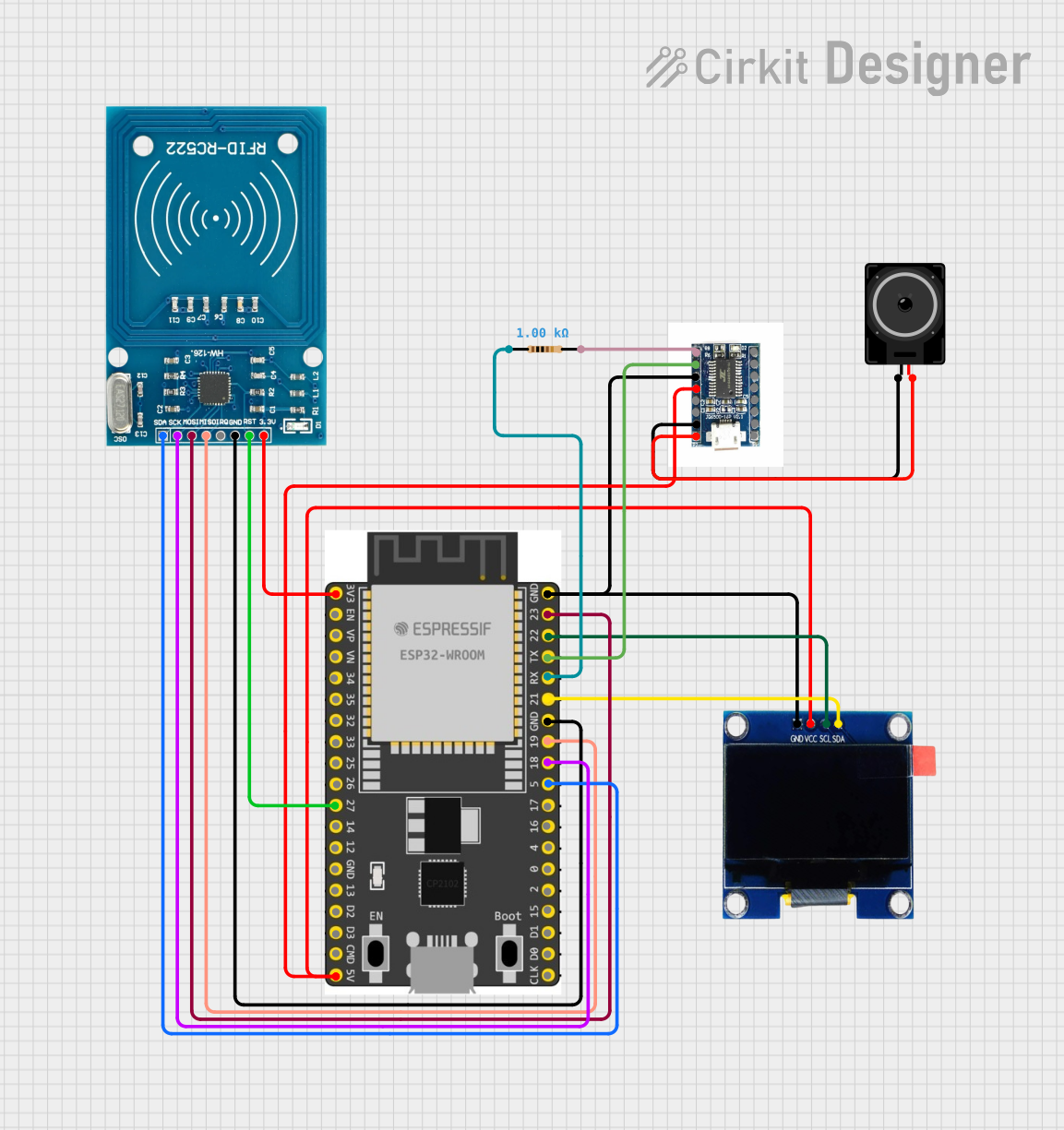
Circuit Documentation
Summary
The circuit in question is designed to integrate an ESP32 Wroom Dev Kit with several peripheral devices, including an OLED display, an RFID-RC522 module, a Neo sound module, a resistor, and a loudspeaker. The ESP32 serves as the central microcontroller, facilitating communication and control between the connected devices. The OLED display provides a visual interface, the RFID-RC522 module enables RFID reading capabilities, the Neo module is used for audio output, and the loudspeaker is driven by the Neo module for sound generation. The resistor is used in the signal path between the ESP32 and the Neo module.
Component List
ESP 32 Wroom Dev Kit
- Description: A development board based on the ESP32 microcontroller, featuring Wi-Fi and Bluetooth connectivity, and a wide range of GPIO pins.
- Pins: 3V3, EN, VP, VN, GPIO 34, GPIO 35, GPIO 32, GPIO 33, GPIO 25, GPIO 26, GPIO 27, GPIO 14, GND, GPIO 13, SD2, SD3, CMD, V5, GPIO 23, GPIO 22, TXD, RXD, GPIO 21, GPIO 19, GPIO 18, GPIO 5, GPIO 17, GPIO 16, GPIO 4, GPIO 0, GPIO 2, GPIO 15, SD1, SD0, CLK
OLED 1.3"
- Description: A small 1.3-inch OLED display for visual output.
- Pins: GND, VCC, SCL, SDA
RFID-RC522
- Description: An RFID reader/writer module for contactless communication using radio frequency.
- Pins: VCC (3.3V), RST, GND, IRQ, MISO, MOSI, SCK, SDA
Neo Sound Module
- Description: An audio module capable of playing sound files, with built-in amplifier for driving a loudspeaker.
- Pins: K1, SPK+, SPK-, K2, K3, DAC_L, DAC_R, VCC, GND, TX, RX, K4, K5, ADKEY, BUSY
Resistor
- Description: A passive two-terminal electrical component that implements electrical resistance as a circuit element.
- Resistance: 1000 Ohms
Loudspeaker
- Description: An electroacoustic transducer that converts an electrical audio signal into a corresponding sound.
- Pins: pin1, pin2
Wiring Details
ESP 32 Wroom Dev Kit
- 3V3: Connected to RFID-RC522 VCC (3.3V)
- V5: Connected to OLED VCC and Neo VCC
- GND: Common ground with OLED, Neo, and RFID-RC522
- GPIO 27: Connected to RFID-RC522 RST
- GPIO 23: Connected to RFID-RC522 MOSI
- GPIO 22: Connected to OLED SCL
- TXD: Connected to Neo TX
- RXD: Connected through a resistor to Neo RX
- GPIO 21: Connected to OLED SDA
- GPIO 19: Connected to RFID-RC522 MISO
- GPIO 18: Connected to RFID-RC522 SCK
- GPIO 5: Connected to RFID-RC522 SDA
OLED 1.3"
- GND: Connected to common ground
- VCC: Connected to ESP32 V5
- SCL: Connected to ESP32 GPIO 22
- SDA: Connected to ESP32 GPIO 21
RFID-RC522
- VCC (3.3V): Connected to ESP32 3V3
- RST: Connected to ESP32 GPIO 27
- GND: Connected to common ground
- MOSI: Connected to ESP32 GPIO 23
- MISO: Connected to ESP32 GPIO 19
- SCK: Connected to ESP32 GPIO 18
- SDA: Connected to ESP32 GPIO 5
Neo Sound Module
- VCC: Connected to ESP32 V5
- GND: Connected to common ground
- TX: Connected to ESP32 TXD
- RX: Connected through a resistor to ESP32 RXD
- SPK+: Connected to Loudspeaker pin2
- SPK-: Connected to Loudspeaker pin1
Resistor
- pin1: Connected to ESP32 RXD
- pin2: Connected to Neo RX
Loudspeaker
- pin1: Connected to Neo SPK-
- pin2: Connected to Neo SPK+
Documented Code
No code has been provided for the microcontroller(s) in this circuit. If code is later supplied, it should be documented here, including descriptions of the functionality implemented, setup and loop routines, and any interrupt service routines or function definitions.