
Arduino Mega 2560 Controlled Servo Motor with IR Remote and PWM Control
View and Edit Project In Cirkit Designer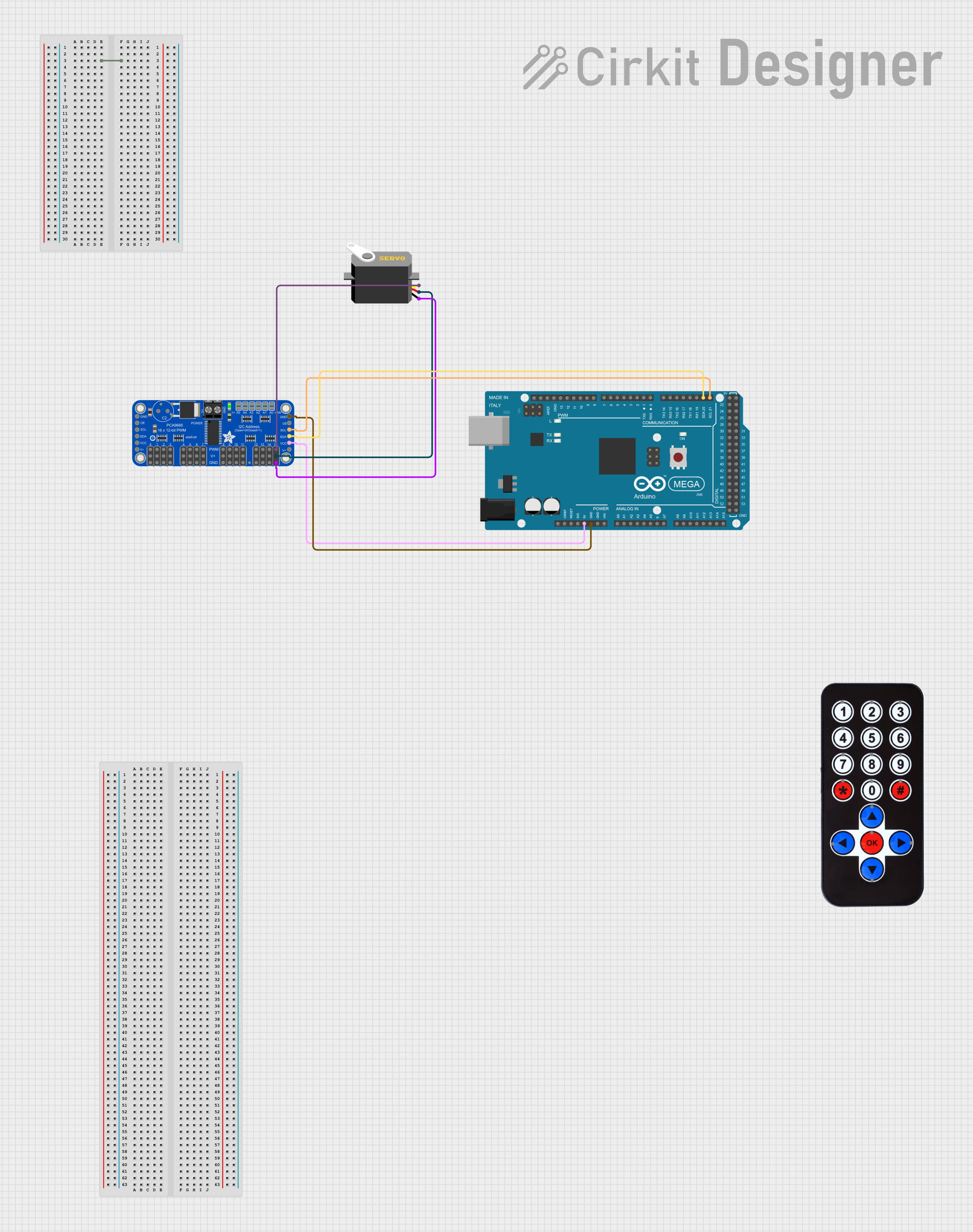
Circuit Documentation
Summary
This circuit involves an Arduino Mega 2560 microcontroller, an Adafruit PCA9685 PWM Servo Breakout, a Servo motor, and an HX1838 Infrared IR Wireless Remote Control. The Arduino Mega 2560 is used to control the PWM signals sent to the Servo motor via the PCA9685 breakout board. The HX1838 IR remote control is used to send commands to the Arduino.
Component List
HX1838 Infrared IR Wireless Remote Control
- Description: An infrared remote control used to send commands wirelessly.
- Pins:
- FFA25D (1)
- FF629D (2)
- FFE21D (3)
- FF22DD (4)
- FF02FD (5)
- FFC23D (6)
- FFE01F (7)
- FFA857 (8)
- FF906F (9)
- FF9867 (0)
- FFB04F (#)
- FF6897 (*)
- FF18E7 (↑)
- FF5AA5 (→)
- FF10EF (←)
- FF4AB5 (↓)
- FF38C7 (OK)
Adafruit PCA9685 PWM Servo Breakout
- Description: A PWM driver board used to control multiple servos.
- Pins:
- 5.0V
- GND
- PWRIN
- PWM7
- PWM6
- PWM5
- PWM4
- PWM3
- PWM2
- PWM1
- PWM0
- VCC
- SDA
- SCL
- OE
- PWM15
- PWM14
- PWM13
- PWM12
- PWM11
- PWM10
- PWM9
- PWM8
Servo
- Description: A servo motor used for precise control of angular position.
- Pins:
- gnd
- vcc
- pulse
Arduino Mega 2560
- Description: A microcontroller board based on the ATmega2560.
- Pins:
- IOREF
- RESET
- 3V3
- 5V
- GND
- VIN
- A0
- A1
- A2
- A3
- A4
- A5
- A6
- A7
- A8
- A9
- A10
- A11
- A12
- A13
- A14
- A15
- D21/SCL
- D20/SDA
- D19/RX1
- D18/TX1
- D17 PWM/RX2
- D16 PWM/TX2
- D15/RX3
- D14/TX3
- D0 RX0
- D1 TX0
- D2 PWM
- D3 PWM
- D4 PWM
- D5 PWM
- D6 PWM
- D7 PWM
- D8 PWM
- D9 PWM
- D10 PWM
- D11 PWM
- D12 PWM
- D13 PWM
- AREF
- SDA
- SCL
- D52
- D50
- D48
- D46
- D44
- D42
- D40
- D38
- D36
- D34
- D32
- D30
- D28
- D26
- D24
- D22
- D53
- D51
- D49
- D47
- D45
- D43
- D41
- D39
- D37
- D35
- D33
- D31
- D29
- D27
- D25
- D23
Wiring Details
HX1838 Infrared IR Wireless Remote Control
- No connections specified in the net list.
Adafruit PCA9685 PWM Servo Breakout
- VCC connected to 5V on Arduino Mega 2560
- SDA connected to D20/SDA on Arduino Mega 2560
- SCL connected to D21/SCL on Arduino Mega 2560
- GND connected to GND on Arduino Mega 2560
- PWM15 connected to pulse on Servo
- 5.0V connected to vcc on Servo
- GND connected to gnd on Servo
Servo
- pulse connected to PWM15 on Adafruit PCA9685 PWM Servo Breakout
- vcc connected to 5.0V on Adafruit PCA9685 PWM Servo Breakout
- gnd connected to GND on Adafruit PCA9685 PWM Servo Breakout
Arduino Mega 2560
- 5V connected to VCC on Adafruit PCA9685 PWM Servo Breakout
- D20/SDA connected to SDA on Adafruit PCA9685 PWM Servo Breakout
- D21/SCL connected to SCL on Adafruit PCA9685 PWM Servo Breakout
- GND connected to GND on Adafruit PCA9685 PWM Servo Breakout
Code Documentation
Arduino Mega 2560 Code
void setup() {
  // put your setup code here, to run once:

}

void loop() {
  // put your main code here, to run repeatedly:

}
Additional Documentation
No additional documentation provided.