Arduino Nano and SX1278 LoRa Communication Module
Circuit Documentation
Summary of the Circuit
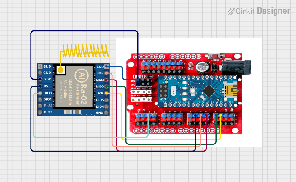
This circuit integrates an Arduino Nano with an I/O Expansion Shield designed for the Arduino Nano and an SX1278 LoRa module. The purpose of this circuit is to extend the capabilities of the Arduino Nano by providing additional I/O pins through the expansion shield and enabling long-range communication through the SX1278 LoRa module. The SX1278 is connected to the I/O Expansion Shield, which is, in turn, interfaced with the Arduino Nano. The connections facilitate SPI communication between the Arduino Nano and the SX1278 module for sending and receiving data over LoRa.
Component List
I/O Expansion Shield For Arduino Nano
- Description: An expansion shield that provides additional I/O pins for the Arduino Nano, making it easier to connect various sensors and peripherals.
- Pins: Analog pins (A0-A7), digital pins (D0-D13), power pins (3.3V, 5V, GND), and I2C pins (SCL, SDA).
Arduino Nano
- Description: A small, complete, and breadboard-friendly board based on the ATmega328P, offering the same connectivity and specs of the Arduino UNO board in a smaller form factor.
- Pins: Digital I/O pins (D0-D13), analog input pins (A0-A7), power pins (3.3V, 5V, GND, VIN), and SPI pins (MOSI, MISO, SCK).
SX1278 LoRa Module
- Description: A wireless communication module that uses LoRa technology to enable long-range transmissions with low power consumption.
- Pins: SPI pins (MOSI, MISO, SCK, NSS), interrupt pins (DIO0-DIO5), power pins (3.3V, GND), and a reset pin (RST).
Wiring Details
I/O Expansion Shield For Arduino Nano
- Analog Pins: A0-A7 connected to corresponding sensors or peripherals as required.
- Digital Pins: D0-D13 connected to corresponding digital devices or modules as required.
- Power Pins: 3.3V and GND connected to power the shield and any low-power peripherals.
- I2C Pins: SCL and SDA available for I2C communication.
Arduino Nano
- Digital I/O Pins: D0-D13 used for digital input and output operations.
- Analog Input Pins: A0-A7 used for analog sensor readings.
- Power Pins: 3.3V, 5V, and GND used to power the board and connected peripherals.
- SPI Pins: MOSI, MISO, and SCK used for SPI communication with the SX1278 module.
SX1278 LoRa Module
- SPI Communication: Connected to the I/O Expansion Shield's D13 (SCK), D12 (MISO), D11 (MOSI), and D10 (NSS) for SPI communication.
- Interrupts: DIO0 connected to the I/O Expansion Shield's D2 for interrupt-driven events.
- Power: 3.3V and GND connected to the I/O Expansion Shield's 3V3(3) and GND for power.
- Reset: RST connected to the I/O Expansion Shield's D9 for resetting the module.
Documented Code
Arduino Nano Code (sketch.ino)
void setup() {
  // put your setup code here, to run once:

}

void loop() {
  // put your main code here, to run repeatedly:

}
This code provides the basic structure for the Arduino Nano's operation. The setup() function is intended for initialization code that runs once at startup, such as configuring pin modes or initializing libraries. The loop() function contains the main logic of the program, which runs continuously after the setup() is complete.
Additional Documentation (documentation.txt)
No additional documentation code was provided for the Arduino Nano.
This document provides an overview of the circuit, including the components used, their wiring, and the embedded code for the microcontroller. Further details can be added to the code and wiring sections as the design and implementation of the circuit progress.