Cirkit Designer
Your all-in-one circuit design IDE
Home /
Project Documentation
Arduino UNO 4x4 Keypad Input Display on 16x2 I2C LCD
Circuit Documentation
Summary
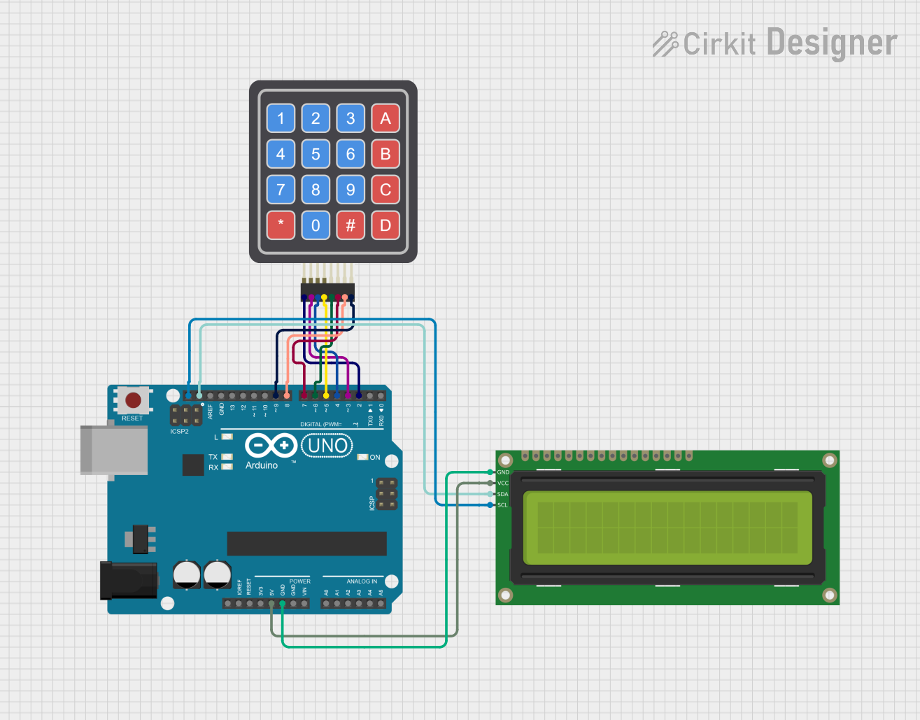
This circuit involves an Arduino UNO microcontroller interfaced with a 4x4 Keypad and a 16x2 I2C LCD. The keypad is used to input characters, which are then displayed on the LCD. The keypad is connected to the digital pins D2 to D9 of the Arduino UNO, while the LCD is connected via the I2C interface (SDA and SCL pins).
Component List
4x4 Keypad (Simulator)
- Description: A 4x4 matrix keypad used for input.
- Pins: R1, C4, R2, C2, R3, R4, C1, C3
Arduino UNO
- Description: A microcontroller board based on the ATmega328P.
- Pins: UNUSED, IOREF, Reset, 3.3V, 5V, GND, Vin, A0, A1, A2, A3, A4, A5, SCL, SDA, AREF, D13, D12, D11, D10, D9, D8, D7, D6, D5, D4, D3, D2, D1, D0
16x2 I2C LCD
- Description: A 16x2 character LCD with I2C interface.
- Pins: GND, VCC, SDA, SCL
Wiring Details
4x4 Keypad (Simulator)
- R1 connected to Arduino UNO D2
- C4 connected to Arduino UNO D9
- R2 connected to Arduino UNO D3
- C2 connected to Arduino UNO D7
- R3 connected to Arduino UNO D4
- R4 connected to Arduino UNO D5
- C1 connected to Arduino UNO D6
- C3 connected to Arduino UNO D8
Arduino UNO
- 5V connected to 16x2 I2C LCD VCC
- GND connected to 16x2 I2C LCD GND
- SCL connected to 16x2 I2C LCD SCL
- SDA connected to 16x2 I2C LCD SDA
16x2 I2C LCD
- VCC connected to Arduino UNO 5V
- GND connected to Arduino UNO GND
- SCL connected to Arduino UNO SCL
- SDA connected to Arduino UNO SDA
Code Documentation
Arduino Sketch
/*
 * This Arduino sketch reads input from a 4x4 keypad and displays the
 * corresponding characters on a 16x2 I2C LCD. The keypad is connected to
 * digital pins D2 to D9 of the Arduino UNO, and the LCD is connected via
 * the I2C interface (SDA and SCL pins).
 */

#include <Wire.h>
#include <LiquidCrystal_I2C.h>
#include <Keypad.h>

// Initialize the LCD with I2C address 0x27 and 16x2 display
LiquidCrystal_I2C lcd(0x27, 16, 2);

// Define the rows and columns for the keypad
const byte ROWS = 4; // Four rows
const byte COLS = 4; // Four columns

// Define the keymap
char keys[ROWS][COLS] = {
  {'1','2','3','A'},
  {'4','5','6','B'},
  {'7','8','9','C'},
  {'*','0','#','D'}
};

// Connect keypad rows and columns to Arduino pins
byte rowPins[ROWS] = {2, 3, 4, 5}; // Connect to the row pinouts of the keypad
byte colPins[COLS] = {6, 7, 8, 9}; // Connect to the column pinouts of the keypad

// Create the Keypad object
Keypad keypad = Keypad(makeKeymap(keys), rowPins, colPins, ROWS, COLS);

void setup() {
  // Initialize the LCD
  lcd.init();
  lcd.backlight();
  lcd.setCursor(0, 0);
  lcd.print("You Entered ");
}

void loop() {
  // Get the key pressed
  char key = keypad.getKey();

  // If a key is pressed, display it on the LCD
  if (key) {
    lcd.setCursor(0, 1); // Move cursor to the second line
    lcd.print(key);
  }
}
Documentation
The example is a numeric keypad connected to the Arduino Uno and the Uno connected to an I2C LCD to display what is typed on the keypad.