Arduino-Controlled RFID Access System with SMS Notification
Circuit Documentation
Summary
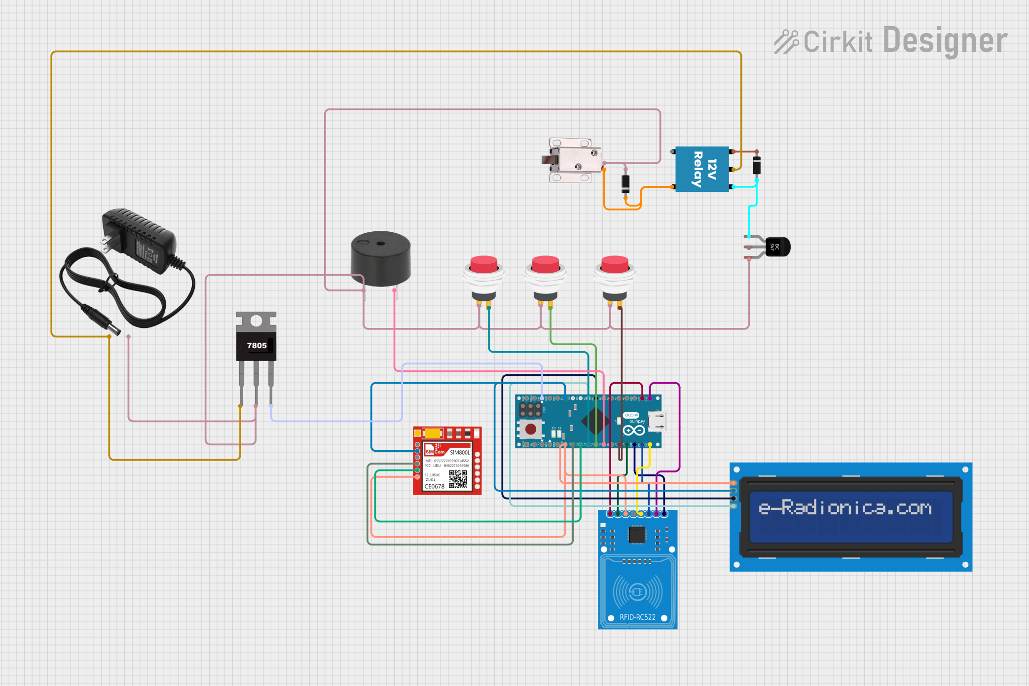
The circuit in question appears to be a microcontroller-based system designed to interface with an RFID-RC522 module, an LCD screen with I2C communication, a SIM800L GSM module, and various other components such as switches, a buzzer, a relay, and a solenoid lock. The Arduino Micro (Rev3) acts as the central processing unit, controlling the interactions between the components. The circuit includes power regulation and switching mechanisms to control the flow of current to the solenoid lock and to signal events with the buzzer.
Component List
RFID-RC522
- Description: An RFID reader/writer module for contactless communication using the 13.56 MHz frequency.
- Pins: SDA, SCK, MOSI, MISO, IRQ, GND, RST, 3.3V
Arduino Micro (Rev3)
- Description: A microcontroller board based on the ATmega32U4.
- Pins: MISO, 5V, SCK, MOSI, RESET, GND, RXLED/SS, D1/TX, D0/RX, D2/SDA, D3/SCL, D4 PWM/A6, D5 PWM, D6 PWM/A7, D7, D8 PWM/A8, D9 PWM/A9, D10 PWM/A10, D11 PWM, D12 PWM/A11, VIN, A5, A4, A3, A2, A1, A0, AREF, 3V3, D13 PWM
LCD screen 16x2 I2C
- Description: A 16x2 character LCD display with an I2C interface module.
- Pins: SCL, SDA, VCC, GND
Sim800l
- Description: A GSM/GPRS module for cellular communication.
- Pins: NET, RST, VCC, RXD, TXD, GND
2Pin Push Switch
- Description: A momentary push button switch.
- Pins: Input +, Output +
Buzzer
- Description: An electronic buzzer for audible signaling.
- Pins: PIN, GND
12V Relay
- Description: An electromagnetic switch used to control a high power circuit with a low power signal.
- Pins: +, -, C, NC, NO
Diode
- Description: A semiconductor device that allows current to flow in one direction only.
- Pins: Cathode, Anode
BC547 Transistor
- Description: A general-purpose NPN bipolar junction transistor.
- Pins: Collector, Base, Emitter
12V Solenoid Lock
- Description: An electromagnetic lock that operates on 12V.
- Pins: VCC, GND
7805
- Description: A voltage regulator that outputs 5V from a higher voltage input.
- Pins: Vin, Gnd, Vout
12V Power Supply
- Description: A power source that provides 12V DC output.
- Pins: +, -
Wiring Details
RFID-RC522
- SDA connected to Arduino Micro D10 PWM/A10
- SCK connected to Arduino Micro D13 PWM
- MOSI connected to Arduino Micro D11 PWM
- MISO connected to Arduino Micro D12 PWM/A11
- GND connected to common ground
- RST connected to Arduino Micro D9 PWM/A9
- 3.3V connected to Arduino Micro 3V3
Arduino Micro (Rev3)
- D2/SDA connected to Sim800l RXD
- D3/SCL connected to Sim800l TXD
- D4 PWM/A6 connected to Push Switch (Instance 1) Output +
- D5 PWM connected to Push Switch (Instance 2) Output +
- D6 PWM/A7 connected to Buzzer GND
- D8 PWM/A8 connected to Push Switch (Instance 3) Output +
- VIN connected to 7805 Vout
- 5V connected to Sim800l VCC and LCD screen VCC
- A5 connected to LCD screen SCL
- A4 connected to LCD screen SDA
- GND connected to common ground
LCD screen 16x2 I2C
- SCL connected to Arduino Micro A5
- SDA connected to Arduino Micro A4
- VCC connected to Arduino Micro 5V
- GND connected to common ground
Sim800l
- RXD connected to Arduino Micro D2/SDA
- TXD connected to Arduino Micro D3/SCL
- VCC connected to Arduino Micro 5V
- GND connected to common ground
2Pin Push Switch (Instance 1)
- Input + connected to common ground
- Output + connected to Arduino Micro D4 PWM/A6
2Pin Push Switch (Instance 2)
- Input + connected to common ground
- Output + connected to Arduino Micro D5 PWM
2Pin Push Switch (Instance 3)
- Input + connected to common ground
- Output + connected to Arduino Micro D8 PWM/A8
Buzzer
- PIN connected to Arduino Micro D6 PWM/A7
- GND connected to common ground
12V Relay
- connected to Diode (Instance 2) Cathode
- connected to BC547 Transistor Collector and Diode (Instance 1) Anode
- C connected to 12V Power Supply +
- NC not connected in this circuit
- NO connected to 12V Solenoid Lock VCC and Diode (Instance 2) Cathode
Diode (Instance 1)
- Cathode connected to 12V Relay +
- Anode connected to BC547 Transistor Collector and 12V Relay -
Diode (Instance 2)
- Cathode connected to 12V Solenoid Lock VCC and 12V Relay NO
- Anode connected to common ground
BC547 Transistor
- Collector connected to 12V Relay - and Diode (Instance 1) Anode
- Base not connected in this circuit
- Emitter connected to common ground
12V Solenoid Lock
- VCC connected to 12V Relay NO and Diode (Instance 2) Cathode
- GND connected to common ground
7805
- Vin connected to 12V Power Supply +
- Gnd connected to common ground
- Vout connected to Arduino Micro VIN
12V Power Supply
- connected to 12V Relay C and 7805 Vin
- connected to common ground
Documented Code
Arduino Micro (Rev3) - sketch.ino
void setup() {
  // put your setup code here, to run once:

}

void loop() {
  // put your main code here, to run repeatedly:

}
Arduino Micro (Rev3) - documentation.txt
The code for the Arduino Micro is currently empty. The setup and loop functions are defined but do not contain any instructions. The user is expected to fill in the code to initialize the components and define the main behavior of the circuit.